


Abstract
A radiative transfer model for the determination of UV radiation on arbitrarily oriented surfaces is validated by spectral measurements taken directly on the inner surface of a cockpit window of an Airbus A321-231 during a flight from Frankfurt, Germany to Málaga, Spain on 23 August 2018. The simulations consider the UV spectral range from 290 to 400 nm and take into account both the measured spectral transmittance of a cockpit window as well as its construction-related orientation. Comparisons are performed for selected route segments with largely cloud-free conditions. The cruising level of the Airbus on these segments was nearly constant between 11.27 and 11.29 km. UV irradiance measurements at the cockpit window give values within a range of 19 and 26 W m−2. The comparison of modelled and measured irradiances show a very good agreement, i.e. the relative differences between simulated and measured values range from −2.1% to +4.3%. In addition, horizontally and vertically oriented sensors are simulated for the same flight. The validation results generally underpin the application potential of the model. As an example of this, UV irradiances incident on differently oriented surfaces, as could occur inside and outside of a future flying taxi on a short-haul flight between Munich and Augsburg at low cruising level, are shown.
Export citation and abstract BibTeX RIS
Acronyms and abbreviations
| AGB | Airport Augsburg, International Air Transport Association (IATA) code |
| AGP | Airport Málaga, International Air Transport Association (IATA) code |
| ALT | Flight altitude above mean sea level |
| AOT | Aerosol optical thickness |
| CL | Cockpit window centre left |
| COT | Cloud optical thickness |
| CR | Cockpit window centre right |
| FAA | Federal Aviation Administration |
| FRA | Airport Frankfurt, International Air Transport Association (IATA) code |
| GND | Ground elevation above mean sea level |
| GS | Ground speed |
| HGT | Flight height above ground |
| RTM | Radiative transfer model |
| TC | True course, angle between track and the direction to geographic north |
| TOC | Total ozone column amount |
| UV | Ultraviolet |
| UVR | Ultraviolet radiation |
| ρUV | UV surface albedo |
| Θr | (Solar) zenith angle of incident direct radiation referred to the normal on the inclined sensor plane |
| Θh | (Solar) zenith angle of incident direct radiation referred to the z-axis in the horizontal coordinate system |
| Ψh | (Solar) azimuth angle of incident direct radiation referred to true north in the horizontal coordinate system |
| δr | Zenith angle of the normal of an inclined sensor referred to the z-axis in the horizontal coordinate system |
| φr | Azimuth angle of the normal on an inclined sensor referred to true north in the horizontal coordinate system |
| ψw | Azimuth angle of the normal on the cockpit window referred to the roll axis of the aircraft |
| λ | Wavelength |
1. Introduction
The level of solar ultraviolet radiation increases with altitude and is therefore significantly elevated at cruising altitudes with respect to ground level [1]. The most energetic component, UV-C (100–280 nm), is filtered by the ozone layer in the upper atmosphere and has no relevance for commercial cruising altitudes, whereas UV-B (280–315 nm) and UV-A (315–400 nm) are only partly filtered by the atmosphere.
However, the UV radiation inside a cockpit of an aircraft differs significantly from the UV radiation outside at the same flight level. The main reason is that the UV radiation inside is affected by the spectral transmission of cockpit windows and by the orientation and position of a surface element receiving the UV radiation. Approaches to quantify the UV radiation inside a cockpit are either direct measurements using UV instruments or numerical simulations based on UV radiative transfer models (RTMs).
Measurements of the UV radiation in cockpits of commercial aircraft have been subject of several studies. Diffey et al [2] used polysulphone film badges to measure the UV exposure for wavelengths below 330 nm on several flights and found no significant exposure. Sanlorenzo et al [3] detected UV-A, but no UV-B radiation inside a turboprop airplane at the pilot's position for different altitudes. Chorley et al [4, 5] found windows with good and poor UV-A attenuation within the same cockpit. Out of 14 flights with several aircraft Cadilhac et al [6] found UV-A radiation only in Boeing 777 cockpits. Schennetten et al [7] found that the UV-A transmittance is strongly dependent on the manufacturer of the window.
Simulations of the UV radiation inside a cockpit require a RTM to account for the effects of inclined surfaces located at certain positions by simultaneously considering the spectral transmittance of a cockpit window. A large number of RTMs have been developed and evaluated which allow for the simulation of solar radiation on inclined surfaces in the solar spectral range (290–4000 nm) (e.g. [8, 9]). Models of this type are usually applied in the field of solar energy. RTMs simulating irradiances on inclined surfaces but confined to the UV spectral range (290–400 nm) are mainly aimed at studying UV effects on the human body at ground and outside of buildings or transport vehicles (e.g. [10–12]). An assessment of the UV-A exposure in cockpits for different flight routes by use of a one-dimensional RTM taking into account a windshield transmittance from Nakagawara et al [13] has so far only been presented by Meerkötter [14].
The articles [2–7, 13, 14] are concerned with the UV radiation in the cockpit and the UV exposure of pilots. The UV exposure of passengers is likely to be negligible in the cabins of today's commercial aircraft. However, it is expected that aviation will change over the next few decades. For example, flying taxis are supposed to relieve the congested streets of big cities and the individual traffic will be partly in the air. Also, a general trend towards larger cabin windows seems to be emerging. There are visions of the future that passengers of flying taxis will have an unclouded view from large panoramic windows. Furthermore, helicopters are expected to fly even faster and higher in the future (e.g. Aircraft of the future [15]). As a consequence, even passengers could potentially be exposed to higher UV levels which means that more people as the number of today's air traffic pilots would be affected. It is clear that new cabin window designs must be accompanied by appropriate UV protection. Nevertheless, the question arises which UV doses people will be exposed to in future flying taxis.
On 23 August 2018 the Deutsches Zentrum für Luft- und Raumfahrt (DLR) in cooperation with Lufthansa carried out UV measurements at a cockpit window inside of an Airbus A321-231 during a flight from Frankfurt (FRA) to Málaga (AGP). This dataset provided an excellent opportunity to compare, for the first time, UV measurements inside a cockpit with simulation results of a RTM developed at DLR. In the following it is shown that the RTM is able to adequately take into account the specific conditions given by the flight altitude, by the spectral transmittance of a cockpit window, and by an oriented sensor inside the cockpit. The results suggest that the RTM could, in principle, also be used to estimate the UV exposure of persons in future aircraft types like flying taxis moving on routes in the lower airspace.
This article is structured as follows: First the measuring instrument and the measured data as well as the RTM and its input data are described. Then the results of the comparison are presented and discussed. Finally, a look into the future is dared. For this purpose, we show simulations of UV dose values, as they could be received by differently inclined surfaces in the interior of a flying taxi on fictitious short-distance routes from and to Munich in different seasons and for an assumption of the window spectral transmittances.
2. Measurements
2.1. Instrument
An ILT950UV spectroradiometer (International Light Technologies, Peabody, MA, USA) and an ILT-RAA4 right angle cosine diffusor as input optic were used to measure in-flight UV radiation. The instrument uses a CCD sensor with 2048 pixels to detect wavelengths from 200 to 450 nm with a symmetrical Czerny–Turner configuration. The wavelength resolution of the system is 0.6 nm (FWHM). The instrument was calibrated for spectral irradiance with an angle of incidence of 0° by the manufacturer against a 30 W Deuterium source and a 1000 W Quartz Tungsten Halogen source which are traceable to NIST std. EH2930 and NIST FEL 1000 W, respectively. This calibration was cross-checked with a CL3 30 W deuterium source (traceable to standards by Physikalisch Technische Bundesanstalt). The cosine response of the input optic was measured for a range of angles of incidence. A mercury–argon source was used for the wavelength calibration. The instrument and a tablet computer used for data acquisition were integrated into a portable case to allow measurements in confined cockpits. A UV fibre optic connects the instrument with the input optic to allow measurements at different positions without moving the case to the exact spot of the measurement. The portable case also includes a receiver to obtain information from the transponder of the aircraft about position and heading which are used to assign a set of aircraft parameters to each measurement. Dark and reference measurements with an optical filter were taken for dark count correction and to assess the stray light in the instrument.
2.2. Window spectral transmittance
For an evaluation of measured UV irradiances inside a cockpit as well as for corresponding model simulations the spectral transmittance of the window in the field of view of a sensor has to be known. In previous model calculations [14] the transmittance of the window was obtained by using measurements performed on an Airbus window by the FAA [13]. For comparing model calculations with UV irradiances measured behind a specified cockpit window, as done in this study, the knowledge of the actual spectral transmittance of this window type is required. Specifically, the spectral transmittance was determined for a sliding side window of an Airbus A321-231 at ground on Málaga Airport on 23 August 2018 under clear sky conditions with direct solar radiation incident on the sensor. As shown in figure 1 this window belongs to a type which is completely blocking UV-B radiation, but is significantly transparent to UV-A for wavelengths greater than about 335 nm. The transmittance was measured for the right sliding window (centre right = CR). However the measurements of solar UV-A radiation were performed on the left sliding window. Due to the solar position it was not possible to perform both measurements on the very same sliding window. Nevertheless we will assume the same transmittance for both sliding windows.
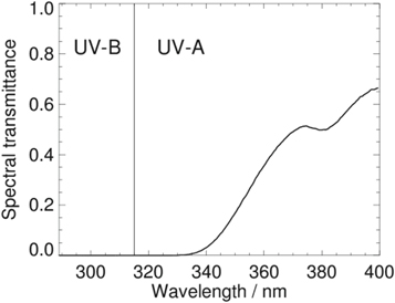
Figure 1. Spectral transmittance of the Airbus 321–231 sliding cockpit window (centre right) in the UV spectral range measured at ground on Málaga Airport on 23 August 2018.
Download figure:
Standard image High-resolution imageThe measured spectral transmittance of the window CR does not take into account the direction of the incoming radiation. If the angle of incidence is large, the radiation has a longer path through the material of the window and is therefore more strongly attenuated than radiation with a smaller angle of incidence. The window transmittance has been measured at ground on Málaga Airport, but the model calculations are performed assuming that the measured transmittance also applies at cruising altitude. Fact is that the ratio of the diffuse to the total irradiance (direct plus diffuse) decreases with altitude. While at the ground this ratio in the order of about 30%–40%, it decreases to about 12%–14% at cruising level which in principal means that the measured mean transmittance of irradiance changes with altitude. Estimations by use of the RTM, however, reveal that these differences are in the order of only a few percent.
2.3. Data selection
Measurement data that were acquired on a flight from Frankfurt to Málaga (AGP) on August 23 2018 were chosen for the model comparison because this flight provided large, mostly unclouded route segments. As mentioned before, only measurements performed at the left sliding window (CL = centre left) are considered for this model comparison. Window CL was made by the same manufacturer as the window with the measured transmittance on the right side of the cockpit. The third condition for the data selection is a solar incident angle referred to the input optic of Θr ≤ 45°. The data from the selected dataset were taken at the inner surface of the windshield to achieve a simple and reproducible position with a large field of view to determine the maximal irradiance. The specific orientation of the cockpit windshield determines the solar incident angle Θr during flight and is therefore an important input parameter for the RTM.
2.4. Orientation of cockpit windows
The simulation of UV measurements demands to specify the orientation of the input optic at the window as well as heading, position and time as precisely as possible. While the latter three are directly logged during the measurement, the former has to be measured separately under stable flight conditions. The UV measurements where conducted on the inner surface of the window by using a mount for smooth surfaces. That means the window and the input optic share the same normal vector and a measurement of the orientation of the window is equivalent to a measurement of the orientation of the sensor. The zenith angle of the window δr, defined as the angle between the normal vector and the zenith direction in the horizontal coordinate system, was measured with a plummet directly in the cockpit under stable flight conditions and gave δr = 59°. The document Flight Deck and System Briefing for pilots [16] contains a plan view drawing of the cockpit from which, by aid of image processing software, the azimuth angles of all cockpit windows were determined. For the lower rear area of the centre window to which the input optics was attached at the time of measurement an azimuth angle of ψw = −67° was derived. Note, in case the window normal vector is pointing forwards and parallel to the roll axis of the aircraft, the azimuth angle is ψw = 0°. The negative value of ψw denotes a counter-clockwise rotation. Thus, the azimuth orientation of the window during flight finally is the actual heading plus ψw.
2.5. Correction of deviation from ideal cosine response
The cosine response of the measuring input optics against the zenith angle Θr of incident direct radiation is known from laboratory measurements. Uncertainties of the measurement due to deviations from a perfect cosine response can therefore be estimated for direct incoming radiation, since the angle of incident is known. In case of diffuse radiation a correction factor has been derived. First, the known deviations from the cosine as a function of Θr, Fdev, are fitted with a polynomial. Then the hemispherical integral ∫Ω over radiances set constant to 1 W m−2sr−1 has been calculated by taking into account the fit-values of the angular dependent deviations Fdev. This results in the correction factor:

π in W m−2 results from the hemispherical integral ∫Ω over radiances set constant to 1 W m−2sr−1 Note, C is an approximation assuming the radiances of diffuse radiation are independent of the zenith and azimuth angles of incident radiation. This is not quite correct, since diffuse radiation incident on the sensor usually is slightly angular dependent. Assuming for example a linear increase (decrease) of the diffuse radiance with Θr up to 20% the value at Θr = 0° would lead to C = 1.23 (1.17). An application of C = 1.21 may nevertheless be justified because the diffuse fraction of UV radiation at flight altitudes above 10 km is only 12%–14% of the sum of direct and diffuse radiation. This relatively low portion of the diffuse component also means that the factor C enters into the correction of measured irradiances with a correspondingly lower weight.
In practice, the correction of the measured irradiances requires the knowledge of the portion of their direct and diffuse components. These components were determined for each measurement point using the RTM. The correction was then made separately for the direct and the diffuse irradiances which were finally added again.
3. Model approach and input parameters
3.1. Radiative transfer model
The method for calculating UV irradiances on arbitrarily oriented virtual sensor planes is based on results of a one-dimensional RTM utilising the doubling-adding method [17], a proven and accurate method for the numerical simulation of the atmospheric radiative transfer (e.g. [18]). The model has successfully been employed in many applications, e.g. [14, 19, 20]. It generates spectral radiances of direct and diffuse radiation with a wavelength resolution of Δλ = 0.5 nm in the UV spectral range from 290 to 400 nm.
Radiances are initially referred to the horizontal plane and calculated for 12 zenith angles including the zenith angle of 0° in upward and downward direction. Zenith angle dependent radiances are azimuthally averaged. The model provides spectral radiances at each boundary of 30 atmospheric layers ranging from the ground to an altitude of 100 km. Discrete flight altitudes are prescribed as layer boundaries.
An extension of the RTM allows for the calculation of UV irradiances on arbitrarily inclined virtual sensor planes. The basic steps are:
- 1.Wavelength integration of angular dependent spectral radiances calculated by the RTM for a given model atmosphere by taking into account the measured spectral transmittance of the A321 cockpit window.
- 2.Discretization of the hemisphere over the inclined sensor plane into solid angle elements along defined zenith and azimuth directions
- 3.Assignment of the downward and upward directed radiances calculated for the horizontal coordinate system to all solid angle elements spanning the hemisphere over the inclined sensor plane
- 4.Hemispherical integration of the radiances incident on the inclined sensor plane
Step 3. is realised by the use of the rotational matrix:
M is the general form of the matrix with α, β, and γ denoting the zenith, roll, and azimuth angles of the normal on the inclined receiver plane with respect to the horizontal coordinate system, respectively. A precondition for step 3. is that the downward and upward directed radiances of diffuse radiation and the downward radiances of direct radiation which are existing for discrete directions pre-defined by the RTM, are described by analytic fit-functions. This has been realised by polynomial fitting.
3.2. Model atmosphere
The main factors affecting the UV radiation on an oriented sensor at flight altitude are the solar position relative to the normal of the sensor plane, the flight altitude, the existence of clouds, a potential snow cover on the ground, and in case of measurements inside an airplane, the spectral transmittance of the windows, their geometry, and the position of a sensor if it is not directly at the window. Since cockpit windows generally block the short-wave UV-B wavelengths where ozone absorption takes place (figure 1), the precise knowledge of the atmospheric total ozone column amount (TOC) is of minor importance. Thus, a constant TOC = 300 DU is assumed for all radiative transfer calculations. Likewise the UV radiation field at cruising level is less sensitive to the aerosol loading in the atmospheric layers near the surface as well as to the vertical profiles of atmospheric temperature, pressure, and air density. Therefore, radiative transfer calculations have been performed assuming the meteorological parameters of the midlatitude summer standard atmosphere [21]. Assumed is also a cloud-free atmosphere according to the conditions along the flight route. Figure 2 shows a map of satellite derived cloud optical thicknesses (COT) from the NOAA Climate Data Record PATMOS-x dataset [22]. For the most parts of the route segments the atmosphere appears as cloud-free, only the mountain chain of the Pyrenees induces clouds structures of higher COT. The atmospheric aerosol composition corresponds to a continental type, the total aerosol optical thickness AOT is set to 0.2 for atmospheres with a lower boundary at z = 0 m MSL. Along the flight route the model AOTs are however reduced because the atmospheric column is cut by an elevated surface terrain. Surface elevations along the flight route are taken from the GTOPO30 Digital Elevation Model [23]. For the UV surface albedo a constant value of ρUV = 0.03 is prescribed, which is a good approximation for snow-free conditions (e.g. [1, 24]).
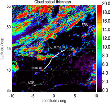
Figure 2. Cloud optical thicknesses over Western Europe on 23 August 2018 at 9:30 UTC based on measurements of the AVHRR instrument onboard the polar-orbiting MetOp-2 satellite as provided by the NOAA Climate Data Record PATMOSx dataset. Thick white lines show the route segments of the flight from Frankfurt (FRA) to Málaga (AGP) treated in this study.
Download figure:
Standard image High-resolution image3.3. Radiative transfer calculations
UV irradiances are calculated for each waypoint where measured UV data are available. Essential for a simulation of spectroradiometer measurements during flight is the knowledge of the solar zenith angle relative to the normal of the sensor plane, Θr. This means that for the flight FRA-AGP the date and time dependent position of the Sun in the Earth fixed system, the aircraft heading, as well as the orientation of the cockpit window (section 2.4) at the point where the input optic of the spectroradiometer has been mounted are taken into account. The wavelength integration of angular dependent spectral radiances is executed by convolving with the measured window spectral transmittance shown in figure 1 and discussed in section 2.2.
UV radiative transfer calculations follow a stepwise procedure. First, irradiances on the inclined sensor plane are pre-calculated for discrete flight altitudes ALT = 10680 m MSL and ALT = 11280 m MSL and for ground elevations of 0.0, 0.5, 1.0, 1.5, 2.0, 2.5 km. These values are covering the range of the real data along the considered flight route segment. In case of the surface elevation area averages over 10 × 10 km2 are taken. Second, UV irradiances at the actual cruising altitudes and surface elevations are calculated at each waypoint by a linear interpolation of the pre-calculated irradiances.
4. Results
4.1. Model validation
In this section UV irradiance measurements performed on the flight route segments shown in figure 2 are compared with results of model calculations for a cloud-free atmosphere taking into account the spectral transmittance of a sliding cockpit window as in section 2.2. Furthermore, simulation results for an upward and downward as well as for a vertically oriented sensor are shown. For the latter, the same azimuth angle φr was assumed as that of the A321 window CL. All curves of the comparison are presented in figure 3(a), (b) shows the solar zenith angle Θr referred to the normal of the inclined sensor.

Figure 3. (a): Measured and model calculated UV irradiances as a function of time for three selected route segments of the flight FRA-AGP on 23 August 2018. The red curve shows the cosine-corrected spectroradiometer measurements, the other coloured curves result from radiation transfer calculations assuming a sensor behind the window inside the cockpit. The area shaded in light-blue covers irradiance values resulting from variations in the range Δδr = 59° ± 2° and Δψw = −67° ± 2°. In case of the Airbus A321 window CL (δr = 59°) and the vertical window (δr = 90°) the azimuth angle is ψw = −67°. (b): Solar zenith angles Θr referred to the normal of the inclined sensor for different angles δr as indicated.
Download figure:
Standard image High-resolution imageMeasured and modelled UV irradiances (upper red and blue curves in figure 3(a) show an excellent agreement. Considering all three route segments, relative differences 100% × (UVmodel−UVmeas)/UVmeas are within the limits of −2.1% and +4.3%. Uncertainties of irradiance measurements by the UV spectroradiometer due to calibration errors are estimated to be in the order of ±11% within the operational temperature range. Deviations from an ideal cosine response are taken into account in section 2.5 and are therefore not included in the given uncertainty.
Slight variations of measured irradiances that simulations do not show could be due to the influence of clouds. Figure 2 shows that clouds could be in the field of view of the input optic of the spectroradiometer, for example in the second half of the second route segment and in the last part of the third segment. However, these cloud effects are not leading to big differences between model results and measurements and their treatment would be a more complex 3D problem going beyond the objectives of this article.
The thickness of the atmospheric column between a ground with low albedo (ρUV = 0.03) and the flight level determines the amount of scattered radiation received by the input optic of the spectroradiometer. For example, the upward UV radiation decreases when an aircraft flies over high mountains, provided they are not snow-covered. However, simulations (not shown) reveal that the terrain elevation along the flight route, varying from 99 to 1660 m, reduces UV irradiances at the cockpit window at cruising level by a maximum of 0.8% when compared with irradiances resulting for a ground elevation of 0 m MSL. Note, measured UV irradiances in the third route segment after the last change of heading (figure 3(a) vary from 21.40 to 21.89 W m−2, i.e. by about 2%. Considering that also small individual clouds may affect the UV measurement, a 2% variation at least indicates that elevations ranging between about 415 and 1446 m MSL along this route segment do not exert a significant effect on UV irradiances at flight level.
The light-blue area in figure 3(a) covers the range of UV irradiance values which would result from an uncertainty in the determination of the zenith and azimuth angles of the window (δr and φr) by ±2°. Irradiances are varying in the order of about ±5% referred to the value valid for the orientation of the sensor fixed at the inclined window with δr = 59° and ψw = −67°.
As shown in figure 3(b) the actual orientation of the measuring sensor leads to maximum UV irradiances due to solar zenith angles Θr < 45° (section 2.3). In the case of a fictitious, horizontally oriented and upward directed sensor (δr = 0°), UV irradiances are reduced and increase slightly with time. Reasons are the generally larger solar zenith angle Θr compared to Θr for the actual sensor orientation and the decrease of Θr with time on the flight southwards towards AGP (figure 3(b)). Steps in the curves for the actual and for the vertically oriented sensor (δr = 90°, ψw = −67°) result from changes of Θr due to changes in aircraft heading (figure 2). In case of the fictitious downward directed sensor (δr = 180°) only diffuse radiation originating from scattering processes at the ground and in the atmosphere below the aircraft are reaching the sensor. Corresponding UV irradiances between 2.3 and 2.8 W m−2 are relatively constant along the flight route segments and amount to about 10% and 13% the measured irradiances composed of direct and diffuse radiation.
4.2. Application example
As mentioned at the beginning, the model is able to calculate the UV radiation on arbitrarily oriented surfaces, outside and inside an aircraft, at arbitrary altitudes in different atmospheres and over every terrain elevation. In the following an example demonstrating the application potential of the model is designed. Calculated are UV irradiances along short-haul flights at relatively low altitude which could result for a future flying taxi.
Assumed is a sensor plane tilted under five zenith angles δr (see figure 4) and moving on the line between Munich centre (lat = 48.13°, lon = 11.55°) and Augsburg Airport (AGB, lat = 48.43°, lon = 10.93°). The distance between Munich and AGB is 56.2 km. The surface normal of the tilted receiver plane points in the direction of the course line. For the route Munich-AGB the true course is TC = 305.95°, for AGB-Munich it is TC = 125.95°. The height of the flying sensor is assumed to be HGT = 400 m above the ground at GND = 500 m corresponding to an altitude of ALT = 900 m above MSL, its speed is 150 km h−1. Altitude changes during take-off and landing phases are not taken into account in this example. To consider different diurnal cycles of the solar zenith angle Θh, calculations were carried out for 21 March and 21 June 2019. Atmospheric parameters and surface albedo are the same as in section 3.2. Although certainly not quite correct for a future flying taxi, the spectral transmittance assumed for a window in front of the sensor was that from section 2.3. The spectral transmittance characteristics may at least be typical in that UV-A radiation is transmitted while UV-B radiation is blocked.

Figure 4. Simulated UV irradiances during short-haul flights between Munich Centre and Augsburg Airport (AGB). Flight height above ground (HGT), ground elevation (GND), ground speed (GS), true course (TC), zenith angle of the inclined receiver (δr), and azimuth angle of the inclined receiver with respect to true north (φr) as indicated. (a): Munich to AGB on June, (b): AGB to Munich on 21 June, (c): as in (a), but for a receiver tilted to the left side, (d): as in (b), but for 21 March 2019. (a)–(d): Long-dashed lines represent irradiances in the free atmosphere. Displayed are individual flights by a solid line starting every half hour. Short-dashed lines result for the same flights by considering an Airbus A321-231 window in front of the receiver. (e): As in (b), but for UV doses behind the Airbus A321-231 window. Each symbol (diamond, cross) represents the UV dose for one single flight from AGB to Munich City, 12 symbols form a curve resulting for 12 flights with starting times at the full hour from 06:00 UTC to 17:00 UTC. UV dose symbols are placed at the half of the flying time. HGT and GS as indicated.
Download figure:
Standard image High-resolution image
UV irradiances are calculated for flights that start every half hour throughout the day, i.e. in March within the time interval from 06:30 to 16:30 UTC and in June from 05:30 to 17:00 UTC. For each individual flight irradiances are calculated every 5.62 min resulting in five waypoints per flight. The total flying time between Munich and AGB is 22.48 min.
Figures 4(a)–(d) compare daytime dependent irradiances obtained for a sensor in the free atmosphere with those for a sensor at the same position but affected by the spectral transmittance of the A321 window. First, it should be noted that all irradiances calculated for a sensor location behind the window are about 30% of those not affected by the spectral transmittance of the window. The diurnal course of irradiances is mainly determined by the changing solar zenith angle of direct radiation referred to the normal of the inclined sensor, Θr. This explains the maxima occurring at local noon for a horizontally oriented receiver plane (figures 4(a)–(d)) and their shifting in the afternoon (morning) on the route Munich-AGB (AGB-Munich), at least for tilt angles allowing direct radiation incident on the sensor (δr = 45°, δr = 90°, and partly δr = 135°). At 09:00 UTC on the route AGB-Munich solar elevation is low. As a consequence a sensor tilted by δr = 45° would measure a higher irradiance maximum compared to the horizontal sensor due to a smaller solar zenith angle Θr (figure 4(b)). The same applies to the sensor tilted by δr = 45° and rotated in azimuth by 90° to the left (φr = 215.95°) for the early afternoon flights on the route Munich-AGB (figure 4(c)). In March, when solar elevations are generally smaller than in June both tilt angles, δr = 45° and δr = 90°, give irradiance maxima higher than those obtained for the horizontal plane (figure 4(d)). In case of the downward-looking sensor (δr = 180°) only diffuse radiation is received. The diffuse radiation component is determined by an isotropically reflecting ground of low albedo (ρUV = 0.03) and by scattering processes in the atmospheric layer between ground and sensor. As a consequence absolute irradiance values are small and hardly dependent on daytime.
Figure 4(e) shows UV doses calculated for two sensors on the route AGB—Munich on June 21 2019, one is flying at the height HGT = 400 m above the ground at GND = 500 m with GS = 150 km h−1, the other moves at ground (HGT = 0 m) with a reduced speed of GS = 80 km h−1. Curves result from connecting single dose values (marked by diamonds and crosses) which are calculated for 12 individual flights with starting times at every full hour from 06:00 UTC to 17:00 UTC. In case of GS = 80 km h−1 the sensor needs 42.15 min for the entire route. The daytime dependent UV doses for δr = 0°, δr = 45°, and δr = 90° behave as in figure 4(b) due to the effect of the solar zenith angle Θr. Since the distance between AGB and Munich is constant UV doses are proportional to GS−1. Depending on daytime and sensor orientation the UV doses resulting for GS = 80 km h−1 are by about 70%–90% higher than the doses for the sensor moving with GS = 150 km h−1.
It is known that the UV radiation depends on height. A low level flight at HGT = 400 m increases the UV irradiances obtained for HGT = 0 m by only 1.6%, 1.9%, and 3.2% for tilt angles δr = 0°, δr = 45°, and δr = 90°, respectively. A flight at HGT = 1500 m (not shown) leads to increases of 5.1%, 6.3%, and 10.5%. As a comparison, at HGT = 10.5 km, the typical flight altitude of a today's commercial aircraft, would correspondingly give the numbers 20.3%, 25.3%, and 53.8%. These results are valid for 11:00 UTC at the location AGB on June 21 2019 and for a true course of TC = 125.95°.
Nevertheless, for a more realistic assessment of the UV exposure in flying taxis further studies would have to be carried out. This for example concerns more realistic assumptions with regard to the window spectral transmittance, the geometry of the windows, and the position of the pilots or the passengers. Geometrical constraints determine the solid angle which is relevant to the UV irradiance received by an inclined skin element. However, for an adequate simulation the design plans of a flying taxi would have to be considered, but they are not available yet. Nevertheless, the intensity of UV radiation inside a cockpit strongly depends on whether the direct sun is entering the cockpit or not [14]. In this respect, the results shown in figure 4 at least give an indication of the expected order of magnitude of UV radiation inside a flying taxi designed with enlarged windows and moving in a cloud-free atmosphere in the lower airspace. Examples how vertical profiles of UV irradiances inside and outside a cockpit are affected by a water cloud layer or a snow cover on the ground are also shown by Meerkötter [14]. An extensive investigation on the effects of various cloud types on the UV radiation in flying taxis would be interesting, but it is beyond the scope of this study. Finally, it should be mentioned that a total UV dose received by a passenger or a pilot ultimately depends on the number of short-haul flights completed. This needs simulations taking into account a large number of different close-to-reality routes as well as more realistic assumptions with regard to the window spectral transmittance.
5. Summary and concluding remarks
Based on spectroradiometer measurements of UV irradiances performed inside a cockpit of an A321 during a flight from Frankfurt to Málaga on 23 August 2018 a RTM has been validated that allows for the calculation of UV irradiances on arbitrarily oriented surfaces. Results of the comparison show a very good agreement. Relative differences between measured and modelled UV irradiances range between −2.1% and 4.3% which are clearly smaller than the uncertainty of the spectroradiometer (11%).
Essential for the simulation of the UV radiation inside an aircraft is the knowledge of the spectral transmittance of its windows. In this study, dealing with the UV radiation inside an Airbus cockpit, the spectral transmittance of one sliding cockpit window has been measured by use of a spectroradiometer which then has been taken into account for the model calculations. However, we learn that different individual spectral transmittance characteristics of the different types of cockpit windows (front, centre, back) due to different material composition should be expected. Thus, it is a priori not justified to transfer the once measured spectral transmittance to all cockpit window types of one aircraft type, even when obtained from one manufacturer. In this work the determined transmittance was used for the same windshield type by the same manufacturer.
This study focusses on the cloud-free atmosphere and it could be shown that the superimposed effects of flight altitude, window spectral transmittance, and the orientation of the input optics on the UV irradiance are correctly simulated by the RTM.
The accuracy of the model simulations mainly depends on how accurately the macroscopic structure and the microphysical properties of real clouds can be described. In this context one should differentiate between homogeneous cloud layers and inhomogeneous cloud structures. Since the 1D RTM is particularly suitable of calculating radiation fields in atmospheres with embedded homogeneous cloud layers, it is justified to conclude that simulations of the UV radiation inside the cockpit of an aircraft flying above or below such cloud layers are reliable. This also applies to flights over snow- and ice-covered surfaces provided the UV surface albedo can correctly be estimated. If the flight route is above a homogeneous cloud layer UV relevant cloud parameters could for example be derived from geostationary satellite sensors like SEVIRI aboard Meteosat Second Generation (e.g. [25, 26]) which allow for a reconstruction or a prediction of the UV dose in the corresponding time interval. Below a cloud layer the UV radiation is significantly reduced anyway.
The 1D RTM certainly reaches its limits in terms of application in atmospheres with inhomogeneous cloud fields. Typical situations arise for flight periods near vertically extended thunderstorm cells or for flights directly above or below fields of broken convective clouds. Also flights between two cloud layers with coverages of less than 100% are most probably difficult to handle. These cases lead into a complex 3D problem and demand to validate and apply a 3D RTM taking into account all relevant macroscopic and microphysical cloud parameters—a challenge for further studies.
The aim of this study was not a medical assessment of the UV radiation measured behind an Airbus cockpit window. The authors would rather like to point to the existence of a RTM, which has a high application potential. By use of an adequate action spectrum and by taking into account the spectral transmittance of any transparent material the model can in principle be used to calculate the UV exposure of persons within an aircraft or of UV sensitive materials at the outer skin of an aircraft at any altitude, but also inside and outside of cars, rail vehicles or buildings. Simultaneously the atmospheric conditions can be varied in a broad range.
For today's air traffic, the model could for example be used to estimate UV exposures on current short, long and medium-haul flights which would narrow the costs of UV measurements during commercial flights. UV simulations shown for a future flying taxi in no way claim to be a reliable and realistic prognosis, especially since the assumptions regarding the spectral window transmittance in detail are certainly not quite correct and flying taxi routes may differ significantly from the assumptions made here. However, the results shown indicate that the model in principle allows for comparative studies of modern transport vehicles under the aspect of UV exposure.
Acknowledgments
The authors would like to thank Andreas Luther ((Deutsches Zentrum für Luft- und Raumfahrt, Institut für Physik der Atmosphäre, Germany) for the critical review of the manuscript and for fruitful discussions. We are grateful to Deutsche Lufthansa for the opportunity to perform in-flight measurements.