
Abstract
Using first-principles calculations, we show that p-doped blue phosphorene can be obtained by molecular doping with 2,3,5,6-tetrafluoro-7,7,8,8-tetracyanoquinodimethane (F4-TCNQ) and 1,3,4,5,7,8-hexafluorotetracyanonaphthoquinodimethane (F6-TNAP), whereas n-doped blue phosphorene can be realized by doping with tetrathiafulvalene (TTF) and cyclooctadecanonaene (CCO). Moreover, the doping gap can be effectively modulated in each case by applying an external perpendicular electric field. The optical absorption of blue phosphorene can be considerably enhanced in a broad spectral range through the adsorption of CCO, F4-TCNQ, and F6-TNAP molecules, suggesting potential of the doped materials in the field of renewable energy.
Export citation and abstract BibTeX RIS

Original content from this work may be used under the terms of the Creative Commons Attribution 3.0 licence. Any further distribution of this work must maintain attribution to the author(s) and the title of the work, journal citation and DOI.
Introduction
Blue phosphorene (BlueP), a monolayer of phosphorus atoms with buckled honeycomb structure, attracts much attention because it combines fascinating features [1]. It is an intrinsic semiconductor with a sizable bandgap in excess of 2 eV [1, 2], which can be modulated by applying an electric field [3], stacking effects [4, 5], functionalization [6–8], doping [9–11], and formation of heterostructures [12–14]. Its mobility is as high as 103 cm2 V−1 s−1 [15], and the thermoelectric figure of merit reaches values of 1.2 (p-doping) and 0.7 (n-doping) already at room temperature [16]. BlueP has potential in important applications such as nanoelectronic devices [17], gas sensors [18, 19], lithium-ion batteries [20, 21], and photocatalysts [22–24]. It can be readily synthesized by epitaxial growth on Au(1 1 1) [25–27] and GaN(0 0 1) [28] substrates. Despite the promises of BlueP as two-dimensional (2D) semiconducting material, however, an effective approach to tune its properties is necessary to facilitate future utilization.
Molecular doping of 2D materials was addressed in the literature for graphene [29–44], MoS2 [45–54], black phosphorene [55–59], arsenene [60, 61], and antimonene [62]. Concerning the effect of molecular doping on the electronic properties, it was shown, for instance, that a bandgap can be opened in graphene, which enables application in devices such as field-effect transistors [32]. Adsorption of decamethylcobaltocene and 3,6-difluoro-2,5,7,7,8,8-hexacyano-quinodimethane molecules on bilayer graphene was studied in [36], achieving a bandgap of up to 0.15 eV. Molecular doping is also a method to control the carrier type and amount in 2D materials without perturbing the band structure (in contrast to traditional atomic doping) [37, 54, 56]. While monolayer graphene grown by ambient-pressure chemical vapor deposition shows p-type characteristics, transition to n-type characteristics can be realized by adsorption of piperidine, making it possible to form a graphene-based p-n junction [42]. Molecular doping can also be used to tune the optical properties of 2D materials. For instance, the photoluminescence intensity of monolayer MoS2 is drastically enhanced by adsorption of 2,3,5,6-tetrafluoro-7,7,8,8-tetracyanoquinodimethane (F4-TCNQ) or 7,7,8,8-tetracyanoquinodimethane (TCNQ) [45]. It can be enhanced by a factor of nine by doping with salicylic acid molecules [52]. While these investigations show that molecular doping is a very powerful approach to tune 2D materials and broaden their range of applications, the technique was not applied to BlueP so far.
In the present work, we therefore explore the effects of molecular doping on BlueP, using first-principles calculations. In addition, application of an external electric field is considered as a tool to modify the electronic properties. Four organic molecules (atomic structures illustrated in figure 1, see also figure S1 in the supporting information (stacks.iop.org/JPhysCM/32/055501/mmedia)) are investigated: tetrathiafulvalene (TTF) and cyclooctadecanonaene (CCO) as examples of electron donors (low ionization potentials of 6.83 and 7.23 eV, respectively [63, 64]), and F4-TCNQ and 1,3,4,5,7,8-hexafluorotetracyanonaphthoquinodimethane (F6-TNAP) as examples of electron acceptors (high electron affinities of 5.24 and 5.37 eV, respectively [65, 66]). We will demonstrate that adsorption of these molecules can yield p- and n-doping without breaking the 2D structure of BlueP. In addition, the ability to absorb sun light can be enhanced significantly, which is critical for the application of BlueP-based materials in energy harvesting.
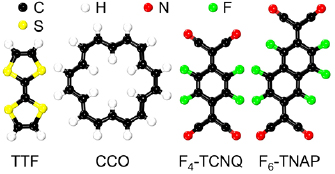
Figure 1. Top views of the atomic structures of TTF, CCO, F4-TCNQ, and F6-TNAP.
Download figure:
Standard image High-resolution imageComputational details
First-principles calculations are performed using the Vienna ab-initio simulation package based on plane-wave density functional theory and the projector-augmented wave method [67]. The energy cutoff of the plane-wave expansion is set to 450 eV and the exchange-correlation functional is treated in the generalized gradient approximation (Perdew–Burke–Ernzerhof form). To describe the long-range interaction between BlueP and organic molecules, the vdW-D3 correction of Grimme is used [68]. The optB86b-vdW functional [69] is found to result in unreasonably large adsorption heights. A large 6 × 6 × 1 supercell is adopted with a vacuum region thicker than 15 Å to eliminate artificial interaction between periodic images. One molecule is added to the supercell, which corresponds to an areal density of 3 × 1013 cm−2. We can neglect substrate effects, because the binding energy between BlueP and the usual substrate, Au(1 1 1), is only 0.11 eV/atom [70]. Brillouin zone sampling on a Monkhorst-Pack 3 × 3 × 1 k-mesh provides good convergence. In the structure optimization the atomic coordinates are relaxed until the Hellmann–Feynman forces are reduced to 0.01 eV Å−1. Absorption spectra are calculated using the Heyd–Scuseria–Ernzerhof (HSE06) hybrid functional [71]. The imaginary part of the dielectric tensor is obtained by neglecting local field effects and approximating the macroscopic dielectric function by the head of the microscopic dielectric matrix [72]. The real part of the dielectric tensor then results from Kramers–Kronig transformation.
Results and discussion
We obtain for pristine BlueP an optimized lattice constant of 3.277 Å. Previously, Zhu et al [1] predicted a lattice constant of 3.33 Å, while Bao et al [20] obtained a value of 3.29 Å. Thus, our calculated lattice constant is in satisfactory agreement with previous results, demonstrating reliability of the methods used in the present work. We determine the favorable adsorption configuration for each molecule (table 1, figure 2) by calculating the adsorption energy Ead = Emolecule + EBlueP − EBlueP+molecule, where Emolecule, EBlueP, and EBlueP+molecule are the energies of the molecule, pristine BlueP, and BlueP with adsorbed molecule, respectively. For each molecule, several high-symmetry adsorption sites are considered (figure S2 in the supporting information). The TTF molecule favors alignment parallel to the zigzag direction of BlueP with Ead = 0.87 eV and adsorption height h = 3.08 Å, the electron-abundant C3S2 rings located above P atoms. The CCO molecule favors a high symmetry configuration with space group C3v (Ead = 1.12 eV, h = 3.50 Å). The aromatic ring of the F4-TCNQ molecule is located directly on top of a P atom to maximize the overlap between its delocalized π electrons and the p electrons of the P atom. In addition, two cyano groups cross the P–P bonds, increasing the electron transfer and binding strength (Ead = 0.87 eV and h = 3.51 Å). Finally, for the F6-TNAP molecule there exist two adsorption sites with Ead = 1.11 eV (2 and 6 in figure S1(d) with h = 3.37 and 3.43 Å, respectively). We choose the configuration presented in figure 2 for the following calculations.
Table 1. Adsorption energy (Ead), adsorption height (h), electron transfer (ΔQ), and injected carrier concentration (n; ΔQ per area).
| Adsorption site | Ead (eV) | h (Å) | ΔQ (e) | n (1012 e cm−2) | |
|---|---|---|---|---|---|
| BlueP–TTF | 6 | 0.87 | 3.08 | −0.11 | 3.3 |
| BlueP–CCO | 6 | 1.12 | 3.50 | −0.04 | 1.2 |
| BlueP–F4-TCNQ | 2 | 0.87 | 3.51 | 0.12 | 3.6 |
| BlueP–F6-TNAP | 2, 6 | 1.11 | 3.37, 3.43 | 0.16 | 4.8 |

Figure 2. Top (upper panel) and side (lower panel) views of the favorable adsorption configurations of TTF, CCO, F4-TCNQ, and F6-TNAP molecules on BlueP. The orange and blue sticks represent upper and lower P atoms, respectively. The white, black, red, green, and yellow spheres represent H, C, N, F, and S atoms, respectively.
Download figure:
Standard image High-resolution imageCharge transfer in the molecule-doped materials may alter the transport and optical performance of BlueP, as revealed for the F4-TCNQ/MoS2 interface in an earlier study [45]. To investigate this question, figure 3 shows the charge density difference isosurfaces obtained for BlueP with adsorbed TTF, CCO, F4-TCNQ, and F6-TNAP molecules. The pink regions denote accumulation of electrons and the gray regions denote depletion of electrons. In the cases of TTF–BlueP and CCO–BlueP (figures 3(a) and (b)) electrons are transferred from the highest occupied molecular orbital (HOMO) to BlueP (P atoms in the contact region), i.e. the TTF and CCO molecules act as electron donors. Bader analysis [73–75] shows that 0.11 and 0.04 electrons are transferred from the TTF and CCO molecules to BlueP, respectively. In the cases of F4-TCNQ–BlueP and F6-TNAP–BlueP (figures 3(c) and (d)) electrons are transferred from BlueP to the lowest unoccupied molecular orbital (LUMO), i.e. the F4-TCNQ and F6-TNAP molecules act as electron acceptors. The transferred electrons are found mainly in the interlayer region between molecule and BlueP as well as on the cyano groups of the F4-TCNQ and F6-TNAP molecules. Large gray isosurfaces at P atoms near the cyano groups reflect strong interaction. Bader analysis [73–75] shows that 0.12 and 0.16 electrons are transferred from BlueP to the F4-TCNQ and F6-TNAP molecules, respectively. The electron transfer from/to the TTF, CCO, F4-TCNQ, and F6-TNAP molecules leads to a carrier concentration of 3.3 × 10¹², 1.2 × 10¹², 3.6 × 10¹², and 4.8 × 1012 cm−2 in BlueP.
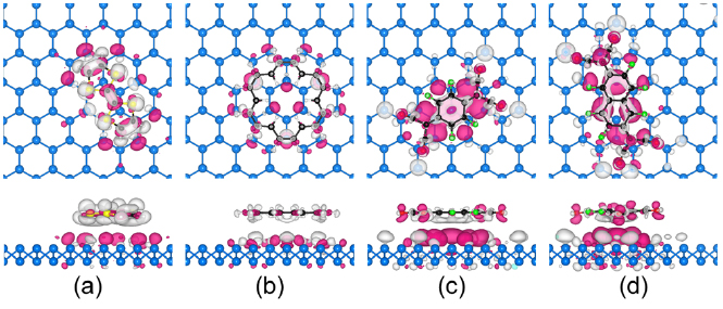
Figure 3. Top (upper panels) and side (lower panels) views of charge density difference isosurfaces (isovalue: 0.0003 e Å−3) for (a) TTF–BlueP, (b) CCO–BlueP, (c) F4-TCNQ–BlueP, and (d) F6-TNAP–BlueP. The white, black, red, green, blue, and yellow spheres represent H, C, N, F, P, and S atoms, respectively. Pink color denotes electron accumulation and gray color electron depletion.
Download figure:
Standard image High-resolution imageFigure 4 shows a projected band structure of pristine BlueP in comparison to results for TTF–BlueP, CCO–BlueP, F4-TCNQ–BlueP, and F6-TNAP–BlueP. Pristine BlueP has an indirect bandgap of 1.94 eV (figure 4(a)), in agreement with the findings of previous investigations [2, 3]. The band structures of TTF–BlueP (figure 4(b)) and CCO–BlueP (figure 4(c)) resemble that of pristine BlueP. However, additional flat bands emerge at 0.27 and 0.97 eV, respectively, i.e. below the conduction band minimum (CBM) of BlueP, reflecting n-doping of the host material. The flat bands represent localized electronic states due to the HOMOs of TTF and CCO. The doping gap (between CBM and HOMO for n-dopants, between LUMO and VBM for p-dopants) of TTF–BlueP is significantly smaller than that of TTF–BlackP (0.73 eV) [56]. For F4-TCNQ–BlueP (figure 4(d)) and F6-TNAP–BlueP (figure 4(e)) the LUMOs of F4-TCNQ- and F6-TNAP appear at 0.39 and 0.45 eV, respectively, i.e. above the valence band maximum (VBM) of BlueP, reflecting p-doping of the host material.

Figure 4. Projected band structures of (a) pristine BlueP, (b) TTF–BlueP, (c) CCO–BlueP, (d) BlueP–F4-TCNQ, and (e) F6-TNAP–BlueP. Red color highlights the contributions of the molecules.
Download figure:
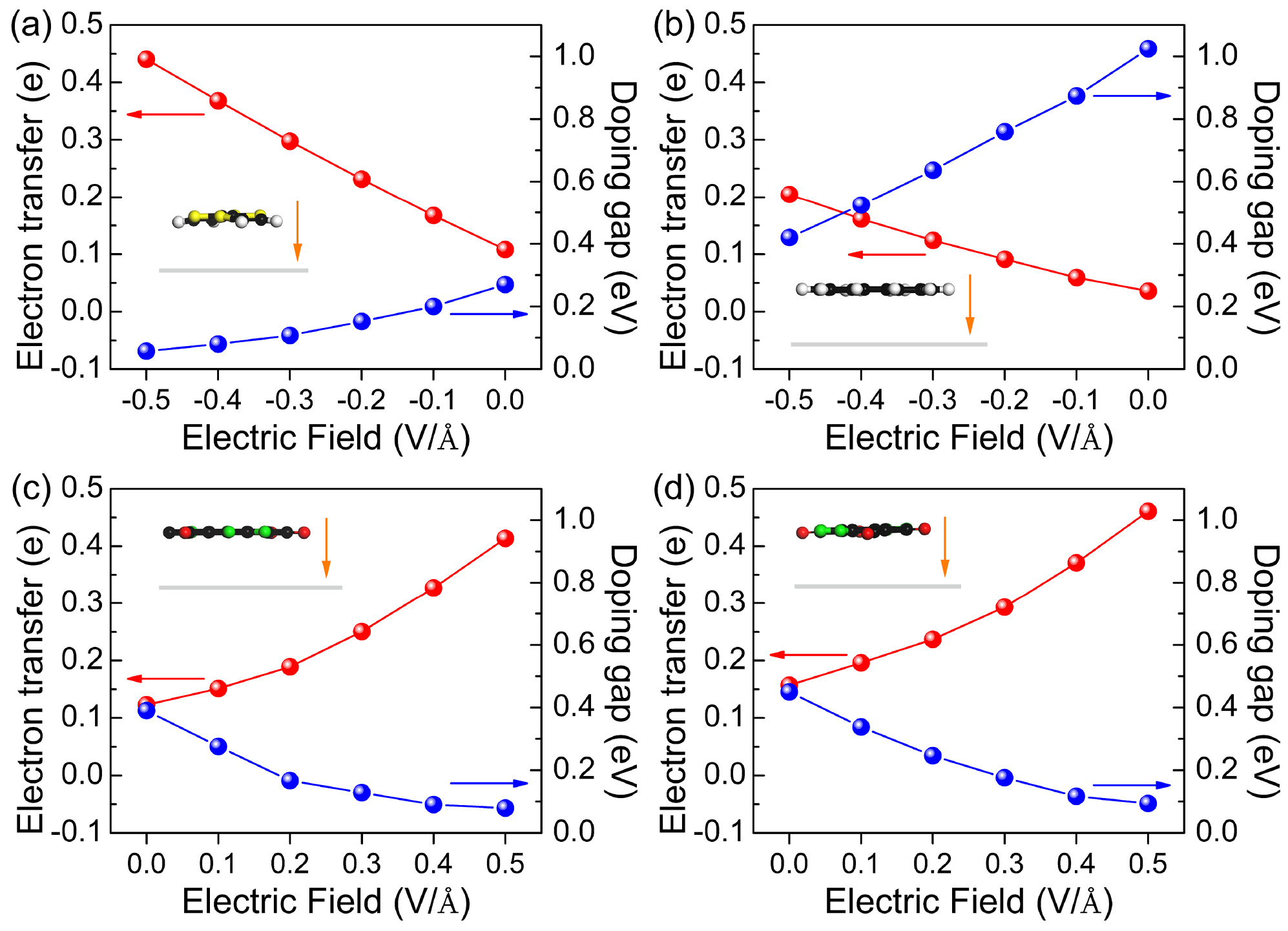
Standard image High-resolution imageThe n-dopants TTF and CCO as well as the p-dopants F4-TCNQ and F6-TNAP induce a large doping gap in BlueP, which makes them to ineffective doping molecules. We next investigate whether an external perpendicular electric field can help to overcome this issue. The dependence of the doping gap and electron transfer on the applied electric field is shown in figure 5 (results after re-relaxing the atomic coordinates in the electric field, which, however, induces only minor structural changes). The strength of the electric field ranges from −0.5 to 0.5 V Å−1 with the positive direction oriented from the molecule to BlueP, see the insets of figure 5. We note that the change in bandgap of pristine BlueP is negligible under such an electric field [3]. For TTF–BlueP and CCO–BlueP the electron transfer is reduced for increasing electric field, i.e., the HOMOs of the molecules shift toward the CBM of BlueP and the doping gaps increase monotonically. Under an electric field of −0.5 V Å−1 (figures 6(a) and (b)) the doping gaps are as small as 57 and 420 meV, respectively, reflecting good controllability. In particular, due to its shallow donor state, TTF–BlueP resembles a typical n-type semiconductor. It turns out that the charge transfer can be reversed by an electric field of 0.3 V Å−1. For F4-TCNQ–BlueP and F6-TNAP–BlueP the electron transfer grows for increasing electric field, i.e. the LUMOs of the molecules shift toward the VBM of BlueP and the doping gaps decrease monotonically. Under an electric field of 0.5 V Å−1 (figures 6(c) and (d)) the doping gaps are as small as 79 and 94 meV, respectively, indicating that shallow acceptor states are formed in both F4-TCNQ–BlueP and F6-TNAP–BlueP, resembling typical p-type semiconductors. We note that the HSE06 functional enhances the doping gaps, while maintaining the general trends described above.
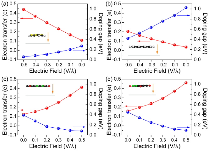
Figure 5. Doping gaps and electron transfer in (a) TTF–BlueP, (b) CCO–BlueP, (c) F4-TCNQ–BlueP, and (d) F6-TNAP–BlueP as functions of the electric field. The insets show the structure under an electric field of strength ±0.5 V Å−1 and the orange arrows indicate the positive direction of this field.
Download figure:
Standard image High-resolution image
Figure 6. Projected band structures of (a) TTF–BlueP and (b) CCO–BlueP under an electric field of −0.5 V Å−1, and of (c) F4-TCNQ–BlueP and (d) F6-TNAP–BlueP under an electric field of 0.5 V Å−1. Red color highlights the contributions of the molecules.
Download figure:
Standard image High-resolution imageIn addition to enhancing the effectiveness of doping, applying an electric field also supports the charge carrier injection and therefore can be beneficial for the device performance. More specifically, according to figure 5, 0.44 electrons are transferred from TTF to BlueP, which leads to an n-type carrier concentration of 1.31 × 1013 cm−2 in BlueP. Transfer of 0.41 and 0.46 electrons from BlueP to F4-TCNQ and F6-TNAP, respectively, leads to p-type carrier concentrations of 1.22 × 10¹³ and 1.37 × 1013 cm−2 in BlueP.
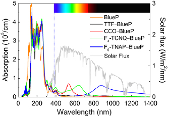
Absorption spectra are shown in figure 7 together with the incident AM1.5g global standard spectrum. Pristine BlueP does not exhibit strong optical absorption in the visible region and, therefore, is not a good photovoltaic material. Similar results are obtained for TTF–BlueP. On the other hand, CCO–BlueP shows a pronounced absorption peak (intensity 7.2 × 104 cm−1) in the visible region centered at 534 nm. For T4-TCNQ–BlueP we obtain more enhancement of the absorption in the visible region with a broader absorption peak (intensity 6.2 × 104 cm−1) centered at 641 nm. Finally, T6-TNAP–BlueP realizes a very broad absorption peak (intensity 6.2 × 104 cm−1) centered at 877 nm. Apart from these additional absorption peaks, which are mainly due to molecular transitions, we observe for all doped materials a redshift of the absorption spectrum with respect to pristine BlueP, which enlarges the overlap with the incident solar flux and thus further enhances their ability to absorb sun light. To quantify the performance of the materials under investigation, we calculate  , where
  is the wavelength,
  is the absorption spectrum, and
  is the incident AM 1.5g global standard spectrum. We obtain for TTF–BlueP, CCO–BlueP, F4-TCNQ–BlueP, and F6-TNAP–BlueP values of 10.6, 37.2, 24.1, and 28.8 W cm−3, respectively. In particular, both CCO–BlueP and F6-TNAP–BlueP therefore turn out to be superior to T4-TCNQ–Arsenene (28.0 W cm−3) [76].
Figure 7. Absorption spectra of pristine BlueP, BlueP–TTF, BlueP–CCO, BlueP–T4-TCNQ, and BlueP–T6-TNAP as calculated with the HSE06 functional. The incident AM1.5g global standard spectrum is shown for comparison.
Download figure:
Standard image High-resolution image
Conclusions
Our investigation of molecular doping of BlueP, based on first-principles calculations, shows that TTF and CCO molecules act as electron donors and lead to n-doping of BlueP while F4-TCNQ and F6-TNAP molecules act as electron acceptors and lead to p-doping of BlueP. The amount of electron transfer, which determines the carrier dynamics and thus the device performance, has been quantified. It turns out that an external perpendicular electric field shifts the HOMO of TTF closer to the CBM of BlueP, resulting in a shallow donor state and effective n-doping of BlueP. Similarly, the LUMOs of F4-TCNQ and F6-TNAP can be shifted closer to the VBM of BlueP, resulting in shallow acceptor states and effective p-doping of BlueP. The application of an electric field also enhances the charge transfer and thus the charge carrier injection into BlueP. CCO, F4-TCNQ, and F6-TNAP molecules induce redshifts of the absorption spectrum of BlueP and enhance the absorption in the visible and infrared regions, which is beneficial for solar energy harvesting. Due to a lack of experimental studies, our results provide important insights into the electronic and optical properties achievable by molecular doping of BlueP. They offer guidelines for the design of electronic, optoelectronic, and photovoltaic devices.
Acknowledgment
Wencheng Tang acknowledges financial support by the National Natural Science Foundation of China (Grant No. 51675100). Jyh-Pin Chou and Alice Hu acknowledge financial support by the City University of Hong Kong (Grant No. 9610336). The research reported in this publication was supported by funding from King Abdullah University of Science and Technology (KAUST).
Supporting information
Structural properties of TTF, CCO, F4-TCNQ, and F6-TNAP. Studied adsorption configurations of TTF, CCO, F4-TCNQ, and F6-TNAP molecules on BlueP.
Notes
The authors declare no competing financial interest.