

Abstract
This paper presents a C-band filtering power divider (FPD) based on a hybrid of spoof surface plasmon polariton (SSPP) and half-mode substrate integrated waveguide (HMSIW). The proposed hybrid circuit is designed by etching subwavelength corrugated grooves in the HMSIW upper wall and has both characteristics of the SSPP and HMSIW structures. It can create the bandpass response and reduce both transverse and longitudinal dimensions of the substrate integrated waveguide structure by nearly 50%. The dispersion and transmission characteristics of the proposed HMSIW-SSPP transmission line are analyzed. The lower and upper edges of the passband can be adjusted independently by tuning the dimensions of the HMSIW and SSPP structures. The presented FPD is fabricated and measured to validate the proposed design procedure. The simulated and measured results are in good agreement. The measured results show that the proposed circuit achieves a bandwidth of 66% from 4 to 8 GHz with better than 10.5 dB return loss and a minimum insertion loss of 1.05 dB.
Export citation and abstract BibTeX RIS
1. Introduction
Surface plasmon polaritons (SPPs) are the electromagnetic waves confined at the interface between a conductor and a dielectric in the optical frequencies [1, 2]. However, the SPP modes cannot directly propagate in the microwave and terahertz frequencies because the metals behave as perfect electric conductors without negative permittivity [3]. In 2004, Pendry et al introduced a new type of transmission line (TL), namely, the spoof surface plasmon polariton (SSPP), by employing a periodic subwavelength structure [4]. The SSPP has the characteristics of SPPs, including electromagnetic field confinement and slow-wave effects at lower frequencies.
A substrate integrated waveguide (SIW) merges the merits of the conventional rectangular waveguides and planar structures, such as low cost, low insertion loss, high power-handling capability, and high-density integration [5]. It has a high-pass response against the low-pass response of the SSPP TL. The SIW structure commonly occupies a large area at lower frequencies. The half-mode substrate integrated waveguide (HMSIW) structure has been introduced in [6] to reduce the SIW's size. The HMSIW can be obtained by bisecting the SIW along its plane of symmetry corresponding to the fictitious magnetic wall of the TE10 fundamental mode. It can almost preserve the field distribution of the original SIW.
Power dividers and bandpass filters are indispensable components in many RF front-ends. A filtering power divider (FPD) is a single component with dual functions. It simultaneously provides the power division and filtering features; and reduces the insertion loss, size, and fabrication cost [7]. Recently, several FPDs have been proposed and researched [8–12]. However, they all suffer from a limited bandwidth, which is a significant drawback in their utilization. There are also other mentions of SSPP and SIW power dividers [13–16], where the designs exhibit a wide bandwidth but not a filtering response. In [17], a mixed TL based on the combination of the SSPP and SIW has been reported to solve the bandwidth issue of the traditional SIW filters. The combination of the SSPP and SIW structures proposed in [17] leads to a bandpass filter with a wide and controllable bandwidth. Moreover, this combination has a shorter wavelength and shows a size reduction of about 50% in the longitudinal dimension. Nevertheless, it requires a thick substrate to produce a sizeable slow-wave effect and hence is not a proper choice for compact circuit applications. Some planar structures have been proposed by periodically etching slots on the top surface of the SIW, and HMSIW [18, 19] to overcome this problem. Guan et al [19], in addition to bandwidth enhancement, presented a HMSIW-SSPP TL that could achieve nearly 50% reduction in both longitudinal and transverse dimensions.
This paper presents an FPD based on the hybrid HMSIW-SSPP structure for C-band applications. In this design, the subwavelength corrugated grooves are etched on the top metal layer of the HMSIW TL to achieve a bandpass response by combining the high-pass and low-pass features of the HMSIW and SSPP structures, respectively. Also, it is demonstrated that the implementation of TLs by the HMSIW-SSPP can lead to a size reduction of approximately 50% in both longitudinal and transverse dimensions compared with the SIW TL. The dispersion and transmission characteristics of the proposed HMSIW-SSPP TL are analyzed. The lower and upper edges of the passband can be adjusted independently by changing the geometric dimensions of the HMSIW and SSPP structures, respectively. To prove the proposed design procedure, the presented FPD is fabricated and measured. The simulated and measured results are in good agreement. The measured results demonstrate a bandwidth of 66% from 4 to 8 GHz with better than 10.5 dB return loss and a minimum insertion loss of 1.05 dB. The proposed FPD has the advantages of wide bandwidth, high selectivity, excellent slow-wave effect and single-layer structure.
2. Analysis and design of HMSIW-SSPP structure
Figure 1 shows the schematic configurations of the SIW, SSPP, SIW-SSPP, and HMSIW-SSPP unit-cells. As shown in figure 1(a), the SIW is configured by two rows of metalized via holes embedded in a planar substrate. Similar to the dielectric-filled rectangular waveguides, the SIW has a high-pass characteristic and a lower cutoff frequency. This cutoff frequency can be adjusted by the distance between two via rows (ws ). In this structure, the fundamental mode is TE10 mode. The cutoff frequency and dispersion relation of the TE10 mode can be achieved by [20, 21]
and
where c is the velocity of light,  is the relative permeability of the substrate,
  is the relative permittivity of the substrate, β is the propagation constant of the TE10 mode, ω is the angular frequency, and
  is the equivalent width of the SIW, which can be calculated by [22]
In (3), d refers to the diameter of the vias, s is their longitudinal spacing, and ws
is their transverse spacing. Also, d and s must be  to guarantee that the radiation loss is negligible [23].
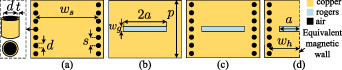
Figure 1. Configurations of (a) SIW unit, (b) SSPP unit, (c) SIW-SSPP unit, and (d) HMSIW-SSPP unit.
Download figure:
Standard image High-resolution imageAs shown in figure 1(b), the unit-cell of the SSPP structure is based on the periodic rectangular slots etched on a metal conductor. p is the period of the SSPP structure, and wg and 2 a are the width and length of slots, respectively. When p and wg are much smaller than the wavelength at the operational frequency, a slow-wave mode can be propagated by periodic slots at microwave frequencies. The SSPP structure displays an excellent low-pass transmission performance with controllable cutoff frequency. The dispersion relation of the SSPP can be obtained by [24, 25]
In figure 1(c), the SIW and SSPP are combined to form the SIW-SSPP structure. This structure has a bandpass filtering response. As shown in figure 1(d), a HMSIW-SSPP with the same characteristics as the SIW-SSPP can be designed by cutting the SIW-SSPP along its plane of symmetry corresponding to the imaginary magnetic wall. wh , which is the width of the HMSIW-SSPP, is approximately half that of the SIW-SSPP. The dispersion relations of the SIW, SSPP, SIW-SSPP, and HMSIW-SSPP structures are analyzed using the eigenmode solver of the commercial software CST Microwave Studio and shown in figure 2(a). These structures are simulated on the Rogers RO4003C substrate with a dielectric constant of 3.55, loss tangent of 0.0027, and thickness of 0.8128 mm. Also, all the metal layers are made with copper, with a thickness of 0.035 mm. The parameters are set as: ws = 20.8 mm, wh = 10.4 mm, wg = 0.9 mm, a = 5.1 mm, p = 2.8 mm, d = 1 mm, and s = 2 mm. It can be observed that the SIW has a lower cutoff frequency and high-pass response versus the SSPP with an upper cutoff frequency and low-pass response. On the other hand, the dispersion relations of the SIW-SSPP and HMSIW-SSPP are almost the same. These hybrid structures present a bandpass characteristic with both lower and upper cutoff frequencies, the same as that of the SIW and SSPP structures, respectively. The dotted red lines define the values of the propagation constant (β) at the center frequency of the passband (6 GHz) for the four structures. As can be seen, the propagation constants of the SSPP, SIW-SSPP and HMSIW-SSPP are about twice of the SIW's propagation constant. Therefore, the SSPP structure and its combinations with the SIW and HMSIW TLs provide an approximately 50% reduction in the wavelength and longitudinal dimension compared to the SIW. Additionally, the HMSIW-SSPP retains nearly all the advantages of SIW-SSPP and a nearly 50% size reduction in the transverse dimension. Figures 2(b) and (c) depict the simulated and theoretical dispersion curves of the SIW and SSPP with different ws and a, respectively. In the SIW, the cutoff frequency is a function of the width of the structure and can be easily shifted to lower frequencies by increasing its size. In the SSPP, the cutoff frequency is a function of the length of the slot and can be easily shifted to lower frequencies by increasing its size. The simulated dispersion curves of the HMSIW-SSPP with different wh and a are shown in figures 2(d) and (e), respectively. The HMSIW-SSPP with half-size has both lower and upper cutoff frequencies. These cutoff frequencies can be adjusted independently by tuning the width of the HMSIW-SSPP TL and the length of the rectangular slots. As can be seen, the cutoff frequencies of this TL are equal to the SIW and SSPP structures. Based on the above discussion, the HMSIW-SSPP TL is a good choice for designing an FPD with wide bandwidth and high selectivity in a single-layer structure.

Figure 2. Dispersion curves of (a) SIW, SSPP, SIW-SSPP, and HMSIW-SSPP structures. (b) SIW with different values of ws
. (c) SSPP with different values of a. (d) HMSIW-SSPP with different values of wh
when a = 5.1 mm. (e) HMSIW-SSPP with different values of a when  mm.
mm.
Download figure:
Standard image High-resolution image3. Analysis and design of FPD based on HMSIW-SSPP structure
The configuration of the proposed FPD based on the HMSIW-SSPP structure is shown in figure 3. This circuit comprises five parts: a microstrip to SIW transition for the input port, an SIW TL (Region I), two HMSIW-SSPP branches (Regions II–IV), four HMSIW to HMSIW-SSPP transitions, and two microstrip to HMSIW transitions for the output ports. Microstrip to SIW and HMSIW transitions are placed with SMA connectors at each port of the FPD for measurement purposes. These transitions use one or two vias with the same diameter as the SIW vias locating at the side of the microstrip taper [26]. To divide the input power into two in-phase signals of the same amplitude, the SIW TL with the length of  = 1 mm is gradually split into two HMSIW TLs with the total length of
  = 69 mm. Twenty-four rectangle-shaped unit-cells are arranged periodically along each HMSIW branch. At first, each HMSIW branch is bent by θ with a bending radius of r; then it is bent by
  with a bending radius of
  . In this design, the lengths of
  (in Region II) and
  (in Region III) are considered to be equal to 14p and 9p, respectively. Therefore, after the selection of θ, the other parameters such as
  , r, and
  can be calculated by
In the proposed FPD, θ =  ,
,  =
=  , r = 112.3 mm, and
  = 20.62 mm. It should be noted that the value of θ is adjustable. In order to show the flexibility of the model, the configuration and simulated scattering parameters of three FPD samples with different values of θ are shown in figure 4. As can be seen, the simulated reflection (S11) and transmission (S21) coefficients are almost unchanged.

Figure 3. Configuration of the proposed FPD based on the HMSIW-SSPP structure.
Download figure:
Standard image High-resolution image
Figure 4. Configuration of the proposed FPD with (a) θ =  ,
,  =
=  , r = 112.3 mm, and
  = 20.62 mm. (b) θ =
  ,
,  =
=  , r = 56.15 mm, and
  = 28.87 mm. (c) θ =
  ,
,  =
=  , r = 37.43 mm, and
  = 48.12 mm. (d) Scattering parameters comparison.
Download figure:
Standard image High-resolution imageThanks to the SSPP structure, a filter function is added to the proposed power divider without changing the other dimensions. This concept is realized by periodically etching subwavelength corrugated grooves on the top metal layer of the HMSIW TLs. Figure 5(a) shows the simulated results of the proposed HMSIW FPD with the SSPP and HMSIW power divider without the SSPP. In addition to adding the filter function, the combination of the SSPP structure and proposed power divider reduces the longitudinal dimension by nearly 50%, as shown in figures 5(b) and (c). This feature was also investigated in section 2 and figure 2(a). The proposed circuit needs an efficient transition from HMSIW to HMSIW-SSPP to obtain a broadband momentum matching. Accordingly, the depth of gradient grooves varies from a1 = 0.1a to a9 = 0.9a with a step of 0.1a. The dispersion curves with different slot lengths a are plotted in figure 6. It can be observed that the dispersion curves gradually shift to lower frequency by increasing the slot length. In other words, the dispersion curves deviate from the HMSIW line and approach the HMSIW-SSPP line. The bandwidth can be easily adjusted in this work by independently tuning the lower and upper cutoff frequencies. The lower and upper cutoff frequency can be set by the width of the HMSIW-SSPP TL (wh
) and length of the slots (a), respectively. To prove the validity of this method, the simulated dispersion curves and transmission coefficients (S21 or S31) of the proposed FPD with different values of wh
and a are presented in figure 7. As can be seen, when wh
and a are increased, the lower and upper cutoff frequencies are moved to a lower frequency. The simulated E-field distributions of the proposed FPD at different frequencies are displayed in figure 8. At 3 and 9 GHz, it is obvious that the energy cannot propagate through the SIW and SSPP when its frequency is smaller than the lower cutoff frequency of the SIW and higher than the upper cutoff frequency of the SSPP, respectively. On the other hand, excellent mode conversions and energy propagation are observed at 6 GHz, which is within the passband. Also, figure 8(d) shows a highly confined and localized field near the interface between the air and metal. The final parameters of the proposed FPD are: wm
= 1.83 mm, ws
= 20.8 mm, wh
= 10.4 mm, wo
= 1.5 mm, wg
= 0.9 mm,  = 5.03 mm,
  = 4.06 mm,
  = 17.36 mm,
  = 11.04 mm,
  = 7.47 mm,
  = 6.12 mm,
  = 0.82 mm,
  = 0.26 mm,
  = 1 mm,
  = 39.2 mm,
  = 25.2 mm,
  = 4.6 mm, a = 5.1 mm, p = 2.8 mm, d = 1 mm, and s = 2 mm.

Figure 5. Comparison between the proposed HMSIW FPD with the SSPP and HMSIW power divider without the SSPP. (a) Simulation results. (b) Electric field distribution of the proposed HMSIW FPD with the SSPP at the passband (6 GHz). (c) Electric field distribution of the HMSIW power divider without the SSPP at the passband (6 GHz).
Download figure:
Standard image High-resolution image
Figure 6. Dispersion curves of the different parts of the HMSIW to HMSIW-SSPP transition.
Download figure:
Standard image High-resolution image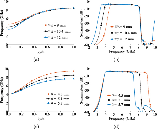
Figure 7. Simulated results of the proposed FPD based on the HMSIW-SSPP structure. (a) Dispersion curves with different values of wh
when a = 5.1 mm. (b) Transmission coefficients (S21 or S31) with different values of wh
when a = 5.1 mm. (c) Dispersion curves with different values of a when  mm. (d) Transmission coefficients (S21 or S31) with different values of a when
  mm.
mm.
Download figure:
Standard image High-resolution image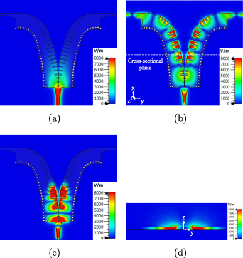
Figure 8. Electric field distribution of the proposed FPD based on the HMSIW-SSPP structure. (a) Top view at lower frequency stopband (3 GHz). (b) Top view at the passband (6 GHz). (c) Top view at upper frequency stopband (9 GHz). (d) Side view at the passband (6 GHz).
Download figure:
Standard image High-resolution image4. Experiment results and discussion
To experimentally verify the proposed FPD based on the HMSIW-SSPP structure in figure 3, we have fabricated a prototype, as shown in figure 9(a). The substrate is a Rogers RO4003C with a dielectric constant of 3.55, loss tangent of 0.0027 and thickness of 0.8128 mm. The results are measured using an HP 8510B network analyzer, which is only calibrated using SMA (3.5 mm) calibration kits. These measurements are taken at a temperature of  C and relative humidity of 25%. The comparison of the simulated and measured results are reported in figures 9(b) and (c), in the frequency band from 2 to 10 GHz. As can be seen, the proposed FPD achieves a 3 dB fractional bandwidth of 66% from 4 to 8 GHz (C-band), a return loss of higher than 10.5 dB, and a minimum insertion loss of 1.05 dB (the 3 dB power division loss is not included). Moreover, the measured phase and amplitude imbalances between the two output ports are within −2.2 to 2 and −0.4 to 0.38, respectively. These results show that the measured results agree well with the simulated ones. There is a slight difference between the simulation and measurement, resulting from the fabrication tolerance and soldering imperfection. A comparison between the proposed FPD and reported power dividers is summarized in table 1, where three conclusions can be made. First, the proposed power divider in this manuscript has a filtering response with high selectivity. Second, the proposed FPD has a wide bandwidth performance, compared with the reported FPDs. Thirdly, it benefits from the easy fabrication process of a one-layer structure.

Figure 9. Fabrication of the proposed FPD based on the HMSIW-SSPP structure. (a) Photograph. (b) Simulated and measured results of S-parameters. (c) Simulated and measured phase and amplitude variation.
Download figure:
Standard image High-resolution image
Table 1. Comparison with previous power dividers.
| Ref. | f0 (GHz) | FBW (%) | RL (dB) | IL (dB) | FR | NoL | TL Tech. |
|---|---|---|---|---|---|---|---|
| [13] | 6 | 60 |

| NG | No | 1 | SIW |
| [14] | 9 | 48.9 |

| 2 | No | 1 | SSPP |
| [15] | 5.5 | 91 |

| 2.1 | No | 1 | SSPP |
[16]
| 5.8 | 131 |

| 1 | No | 1 | SSPP |
| [8] | 4.8 | 12.5 |

| 1 | Yes | 2 | SIW |
| [9] | 6.7 | 8 |

| 2.1 | Yes | 2 | SIW |
| [10] | 5.82 | 15.8 |

| 1.2 | Yes | 1 | SIW |
| [11] | 9.1 | 19.8 |

| 1.2 | Yes | 1 | QMSIW |
| [12] | 2 | 12.5 |

| 1.1 | Yes | 1 | SSPP |
| This work | 6 | 66 |

| 1.05 | Yes | 1 | HMSIW-SSPP |
Ref: reference; FBW: fractional bandwidth; RL: return loss; IL: insertion loss; FR: filtering response; NoL: number of layers; Tech: technology; NG: not given;  : simulation results.
5. Conclusion
In this paper, a C-band FPD based on the hybrid HMSIW-SSPP structure has been proposed. Both features of power division and filtering are provided without increasing the circuit size. The filtering function has been realized after adding the SSPP to the HMSIW structure. For this work, a periodic subwavelength structure has been etched on the top cover of the HMSIW TL. The lower and upper edges of the passband can be adjusted independently by tuning the dimensions of the HMSIW and SSPP structures. The HMSIW-SSPP combination reduces both transverse and longitudinal dimensions of the SIW structure by nearly 50%. Good agreements can be observed between the simulated and measured results. These results demonstrate the ability of the introduced FPD in terms of wide bandwidth, high selectivity, excellent slow-wave effect, and single-layer structure. Due to these advantages, this FPD can play an essential role in mobile and satellite communications and weather radar systems.
Data availability statement
All data that support the findings of this study are included within the article (and any supplementary files).