

Abstract
The paper investigates the effect of the location and size of piezoelectric patches in a composite multilayer plate on the energy input/output when the plate acts as a sensor, actuator, or an energy harvester. It is shown that whether the process is low frequency (static) or higher frequency, for any size of the piezoelectric patches there is always one location where the energy input/output reaches a maximum. In addition, it is shown that for a dynamic vibrational loading the energy input/output is extremely sensitive to the operating frequency. If the operating frequency is just below the systems resonant frequency (corresponding to the length and position of the patches) the best location for the maximum energy input/output is significantly different from the best location when the operating frequency is just above the systems resonant frequency. In other words, a very small change in the systems operating frequency in the vicinity of the resonance frequency can make a significant effect on the best locations for the patches for the energy input/output.
Export citation and abstract BibTeX RIS
1. Introduction
Recent advances in wireless and micro-electro-mechanical systems (MEMS) has increased the demand for portable electronics and wireless sensors, making power supply of these portable devices a crucial issue. Harvesting ambient energy from external sources can become one of the solutions of this problem. One of the ways of harvesting external energy is by using piezoelectric materials to convert mechanical energy from an external source and use it to provide power for electronic devices [1, 2].
There are three typical ways of energy conversion: electromagnetic, electrostatic and piezoelectric [3]. Since piezoelectric devices have the highest energy density and more flexibility to be integrated into a system, energy harvesting, sensing and actuating with piezoelectric materials are the most widely used and investigated both theoretically [4–8] and experimentally [9–11].
Depending on the mechanical energy source different configurations of piezoelectric energy harvesting units have been investigated. For energy harvesting from ambient vibrations unimorph or bimorph cantilever configurations are the most studied structures with piezoelectric ceramic thin films or plates incorporated into the structure. The stress induced in a cantilever in this case is concentrated near the clamped end and the nonstressed part of the piezoelectric layer nearly does not contribute to power generation. Theoretical and experimental studies show that a 'tapered' or triangular-shaped cantilever can produce more even strain level and more energy output throughout. A PZT bimorph cantilever of length 1.75 cm was experimentally studied in [3] to harvest energy from low level vibrations for powering wireless sensor nodes. With a proof mass attached to the tip of the cantilever to lower the resonance frequency, the structure was driven at 100 Hz, the natural frequency of the energy harvester, and achieved 60  W of power. In another experiment [12] a PZT-5H cantilever with dimensions of 63.5 mm
  60.3 mm
  0.27 mm was driven on an electromagnetic shaker at 50 Hz (the resonance frequency of the cantilever) charging a 1000 mAh NiMH rechargeable battery to 90% of its capacity within 22 h. The energy harvesting performance of trapezoidal and rectangular PZT cantilevers was investigated in [13]. At the resonance frequency (140–180 Hz) 24.2 mW of power was obtained with the trapezoidal PZT cantilever whereas 8.6 mW was obtained with the rectangular one.
Different approaches have been employed to maximize the performance including the choice of piezoelectric material and the configuration [14]. One of the solutions is frequency tuning of the piezoelectric element with the external source and maximizing the converted energy using the concept of resonance [15]. Tuning can be achieved by changing the thickness ratio of the piezoelectric patch and the host element [16]. Using finite differences, controlling the shape of a laminated beam by an optimally placed piezo actuator for minimizing the maximum deflection is studied in [17, 18, 19].
The energy output/input can be extremely sensitive to the length and location of the piezoelectric patches. A question arises how these parameters are interconnected in generating maximum energy input/output of the structure. Is there a location for the patches on the host element where the structure performs the best as a sensor, actuator or energy harvester? Similar question arises when the structure is in dynamic operating environment. It is known that energy input/output can be maximum/minimum when the structure is in the resonance condition [20]. In this case also the patches lengths and locations can significantly affect the energy input/output. To the best of our knowledge these questions have not been addressed and need to be investigated.
2. Statement of the problem
We consider a composite piezoelectric structure consisting of a plate-layer substrate of length L in x1 direction, a unit width in x2 direction assuming that all the unknown functions are independent of x2 and two piezoelectric patches of length lp < =L running the full width of the plate, perfectly bonded to its top and bottom surfaces (figure 1). The substrate can be a conductor for generating charge. The position of the patches is defined by a and b = a + lp and hp /2 and hm are the thicknesses of the piezoelectric patches and the substrate. The top and bottom surfaces of the piezoelectric patches are metalized to form electrodes that can be wired in series. To achieve this they are poled in opposite directions so that they produce electric fields in the same direction (figure 1). In the case of a parallel connection, piezoelectric layers are poled in the same direction and produce electric fields in opposite directions. The electrodes covering the opposite faces of the piezoelectric layers are assumed to be thin compared to the overall thicknesses of the structure so that their contribution to the thickness can be neglected.

Figure 1. Schematic of the plate-layer with two piezoelectric patches perfectly bonded to the top and bottom surfaces.
Download figure:
Standard image High-resolution imageThe poling directions of the piezoelectric patches are perpendicular to the planar direction. This means the piezoelectric elements are operating in the (31) mode, corresponding to the piezoelectric charge constant d31 which describes the induced polarization in the poled direction per unit stress applied in stress direction.
Assuming a driving harmonic force  , where
  is the frequency, the transverse displacements in the regions
  ,
,  and
and  can be written in the form
  , with
  corresponding to each region. Introducing dimensionless parameters
  ,
,  ,
,  and
and  the equations describing forced vibrations of a mid-plane transverse deflections of a Kirchhoff–Love plate-layer take the following form:
where 


 are the mass densities,
  the damping coefficients, Di the stiffness constants, (
 ), for regions
  ,
,  ,
,  , with
  ,
, 


![$\left.+ E_m\left(\frac{h_m}{2}\right){}^3\right]$](https://content.cld.iop.org/journals/0022-3727/52/44/445501/revision2/dab37beieqn029.gif) ,
,  and
and  ,
,  . Em and Ep are the Young's moduli for the substrate and the piezoelectric patches, and
  and
and  the Poisson ratios.
The constitutive equations for the piezoelectric patches and the substrate are [15]

where the subscripts 1 and 3 represent the direction along which the corresponding parameter is measured,  and
and  are the stresses,
  and
and  are the strains (superscripts p and m indicating the piezoelectric patches and the plate), d31 is the piezoelectric constant coefficient, E3 the electric field, D3 the electric displacement and
  the permittivity at constant strain.
The total energy of the system can be written as:
where
and  indicates the complex conjugate. It follows from the constitutive equation (4) that the expression for the total energy in dimensionless parameters can be written as
where  and
and  is the dimensionless electro-mechanical coupling factor. Using the equations of motions of a composite plate and boundary conditions the total energy of the system can be expressed via the displacements:
where 
![$ C_1=\frac{d_{31} E_p}{2}\left[ \left(h_p+{h_m}/{2}\right){}^2-\left({h_m}/{2}\right){}^2\right],$](https://content.cld.iop.org/journals/0022-3727/52/44/445501/revision2/dab37beieqn044.gif)


and  is the electro-mechanical coupling factor,
  , (
, ( ) are related to the displacements as

where  is the ith component of the vector p = (1,B,1) and constants
  are found from satisfying boundary conditions at
  . The total energy (8) can be used to analyze the structure as an actuator, sensor and an energy harvester, where Q1, Q2 and Q3 are actuating, sensing and energy harvesting coefficients [4, 5]. We will investigate
  , where D is the domain of
  , Q1 and Q2 can be investigated in a similar way.
Analogous to a parallel plate capacitance the generated charge can be expressed as  where
where  is the voltage,
  is the charge. Writing
  for the uniform electric field in terms of the electric potential difference, the generated charge can be calculated from (8) as follows:
Note that the first term inside the brackets in (13) is the amplitude of the charge  generated by the applied voltage
  and the second term describes the amplitude of the charge
  generated by the applied force
  Thus
Thus
and the capacitance is
Then the generated voltage and the generated electrical energy amplitude due to applied mechanical force q0 can be calculated by
3. Discussion
3.1. Choice of piezoelectric material
The selection of a certain piezoelectric material for a specific energy harvesting applications is determined not only by the piezoelectric properties but also the specific design requirements such as the application frequency and the way mechanical energy is supplied into the structure.
Apart from good piezoelectric properties, piezoelectric ceramics are commonly selected in energy harvesting devices due to their low cost and ease to be incorporated into a energy harvesting structure. PZT is the most frequently used piezoelectric ceramic possessing excellent piezoelectric properties and high Curie temperature (the critical temperature above which piezoelectric a material loses piezoelectricity). It has been expanded into a large family of ceramics, including PZT-5H and PZT-5A, able to exhibit a broad range of properties.
Although piezoelectric ceramics are rigid and brittle and less capable of sustaining large strain, overall, they can provide a higher power output than naturally flexible piezoelectric polymers. Their power output normally is of the order of milliwatts and the application frequencies of PZT ceramic-based harvesters are usually 50 Hz or higher.
Piezoelectric polymers on the other hand are flexible, which makes them resilient to mechanical shock and allows them to be easily mounted to curved surfaces. Piezoelectric polymers, such as PVDF, have been investigated for example for piezoelectric energy harvesting from wearable items, such as shoes and backpacks [21]. Although piezoelectric polymers generally provide smaller power output, at a magnitude of microwatts or nanowatts, in some applications they may generate better power output than PZT ceramics [22].
Here for numerical calculations of the amplitudes of the generated charge  the piezoelectric PZT-5H has been taken with material parameters


 and for the host plate silicon (Si) is chosen with material parameters
 kg m−3. The Poisson's ratios are taken
 and
and  . The dimensionless length of the parches is
  . Mass proportional damping of 1% is taken. The numerical calculations have been carried out for the amplitudes of the generated charge which from the second equation in (14) can be written in the following dimensionless form:
3.2. Static case
It is worth first to look at the dependence of the harvested charge on the position of the piezoelectric patches for a static case when  For structures both simply supported at both ends and simply supported at one end and clamped on the other there is always a position where the piezoelectric harvester generates a maximum charge under the external static force q0 (figures 2(a) and (b)).

Figure 2. The generated charge for the static system for different lengths of the piezoelectric patches when the host is (a) simply supported, (b) simply supported at one end and clamped on the other ( ).
).
Download figure:
Standard image High-resolution imageThe increase between minimum and maximum harvested charge can be significant. For a simply supported host plate (figure 2(a)), when l = 0.2 the increase can be up to  depending on the position of the patches. For l = 0.4 the increase can be up to
  , and for l = 0.5 up to
  .
.
For the host plate simply supported at one end and clamped on the other these differences are more dramatic, declining rapidly as the patches move beyond the position of maximum harvesting (figure 2(b)).
Figures 3(a) and (b) show that the maximum charge is not necessarily harvested when the patches are at the location where the maximum displacement has its highest value. For example, in the case of simply supported plate with  the maximum charge is harvested when the patches are located at
  (figure 2(a)) whereas the maximum displacement has its highest value when
  (figure 3(a)).
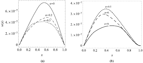
Figure 3. The displacements with the piezoelectric patches at different locations for l = 0.4 (a) simply supported host, (b) simply supported at one end and clamped on the other.
Download figure:
Standard image High-resolution image3.3. Dynamic vibrational case
The question is now how the energy outcome changes in a dynamic vibrational case when the external vibrating frequency is in the close vicinity of the first resonance frequencies shown for different boundary conditions in figures 4 and 5 as a function of the location of the piezoelectric patches. For given parameters of the host plate its resonance frequency is 3.75 corresponding to 476 Hz and the PZT-5H patche's resonance frequency is 101 Hz. Figure 4 shows that for a simply supported host plate the resonance frequencies have a single minimum value for piezoelectric patches of length  and a single maximum when l > 0.5. For simply supported at one end and clamped on the other host plate the resonance frequencies always have a single minimum value. In the first case these extremal positions coincide with the position of the maximum value of the harvested charge for a static plate. In the second case they are slightly shifted from these positions.

Figure 4. First resonance frequencies for different locations and lengths of the piezoelectric patches,  for a simply supported host.
Download figure:
Standard image High-resolution image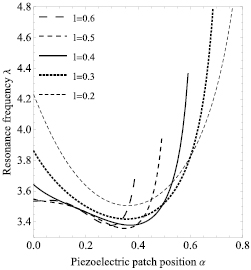
Figure 5. First resonance frequencies for different locations and lengths of the piezoelectric patches,  for a simply supported at one end and clamped on the other.
Download figure:
Standard image High-resolution imageFor a simply supported host plate and the piezoelectric patches of length l = 0.4 attached at  the corresponding resonance frequency is
  (figure 4). The generated charge in this case has a well-defined maximum value for the external vibrating frequency
  just under the minimum resonance frequencies. When the external vibrating frequency is
  , just above the corresponding resonance frequency, the generated charge at the same location
  receives a minimum value, also well demonstrated in figure 6(b). On the other hand this frequency is resonant for two locations (due to the symmetry of the boundary conditions in this case) of the patches hence there are two maximum peaks for the harvested charge but at different locations for the patches.
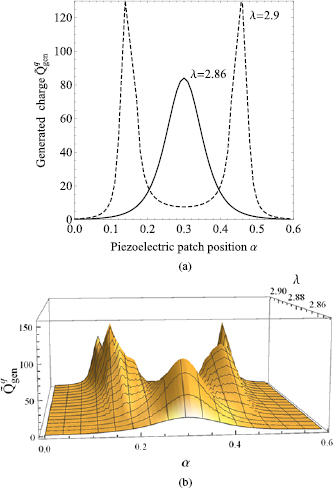
Figure 6. (a) The generated charge at two near-resonance frequencies. (b) The generated charge as a function of frequency and location of the piezoelectric patches ( ).
).
Download figure:
Standard image High-resolution imageSince the pattern of resonance frequencies (figure 4) change for the piezoelectric harvesters with length  , the effect of the change in vibrating frequency at the maximum of the harvested charge changes as well. For piezoelectric patches with l = 0.5 the harvested charge is minimised when the vibrating frequency is just below the resonance frequency
  corresponding to the location of patches
  (figure 7). At this same location the harvested charge changes into maximum with slight change in the external vibrating frequency becoming just above the resonance frequency.

Figure 7. (a) The generated charge for two near-resonance frequencies. (b) The generated charge as a function of frequency and position of the piezoelectric patches (l = 0.5).
Download figure:
Standard image High-resolution imageFigures 8(a) and (b) show a similar result for l = 0.7. The resonance frequency at  is
is  . When the vibrating frequency is below the resonance frequency (
 ) the generated charge has a minimum value and when the vibrating frequency exceeds the resonance frequency (
 ) the generated charge has a maximum value at the same location of the harvester
  .
.

Figure 8. (a) The generated charge for two near-resonance frequencies. (b) The generated charge as a function of frequency and the location of the piezoelectric patches (l = 0.7).
Download figure:
Standard image High-resolution imageNumerical calculations have been carried out also for a piezoelectric soft polymer PVDF with material parameters 

 ,
,  . The first resonance frequencies for all the lengths of the piezoelectric patches in this case lie within a narrower region 3.01 and 3.13 (figure 9). Following the discussion carried out above, it can be noticed that as in the case of PZT-5H patches, for l = 0.2 and l = 0.3 the harvested charge will have a maximum value if the external vibrating frequency is just under the resonance frequencies. If the external vibrating frequency becomes just above the corresponding resonance frequencies, the generated charge at the same location will receive a minimum value. For l = 0.4 and l = 0.5 the pattern of resonance frequencies in this case (figure 9) is different from that for the structure with PZT-5H patches (figure 4). In this case for these lengths of the PVDF patches the generated charge will have a minimum value for vibrating frequencies just below the resonance frequencies and a maximum value for vibrating frequencies just above the resonance frequencies. For
  the pattern of achieving maximum harvested charge will be similar to the case for the harvester with PZT-5H patches.

Figure 9. First resonance frequencies for different locations and lengths of the PVDF piezoelectric patches,  for a simply supported host.
Download figure:
Standard image High-resolution image
4. Conclusion
The investigation carried out in this paper allows to determine the location for piezoelectric patches hosted by a non-piezoelectric plate-layer to maximize the performance of the composite acting as a sensor, actuator or an energy harvester. The expression of the total energy has been derived and used for investigating the converted energy for any length of the piezoelectric patches. The results show that for any size of the piezoelectric patches in the composite plate both for a low frequency (static) and higher frequency processes there is always one location where the energy input/output reaches maximum. In addition, it is shown that for a dynamic vibrational loading the energy input/output is extremely sensitive to the operating frequency. If the operating frequency is below the systems resonant frequency, (corresponding to the length and position of the patches), the best location for maximum energy input/output is drastically different from the best location when the operating frequency is just above the systems resonant frequency. In other words, if the systems operating frequency is close to the resonant frequency the composite does not necessarily generate maximum energy imput/output. Depending on the length of the piezoelectric patches the maximum energy output can be achieved if the operating frequency is just under or just above the corresponding resonance frequency.
The discussion carried out for energy harvesting can be extended for sensing and actuating coefficients. In particular the first term in brackets in (13) can be used for investigating the structure for sensing properties. In order words  describes the structure as a sensor. On the other hand the middle term in (8) with the coefficient Q2 can be used for investigating the system as an actuator
  . The numerical calculations have been carried our for sensing and actuating properties as well. As expressions (9) and (10) for the sensing and actuating coefficients Q1 and Q2 suggest, the results are qualitatively similar to those for the harvesting coefficient Q3 in (11) and the same discussion can be applied to sensing and actuating properies of the structure.