
Abstract
Combining super-resolution structured illumination microscopy (SIM) and lattice lightsheet microscopes (LLSMs) has always been an ideal approach for high spatiotemporal resolution in 3D applications. We propose a simpler method to perform 2D-SIM with three phases, which is 5/3 faster and less sensitive to optical alignment compared to 3D-SIM in LLSM. In this research, we modify the original square lattice lightsheet to become an ideal pattern for the 2D-SIM by filtering the illumination pattern on the back pupil of the excitation objective. We show that the generated lattice pattern is consistent in the experiment and the simulation. We achieved a spatial resolution of 184 ± 28 nm, 244 ± 48 nm and 384 ± 20 nm in the x, y and z directions, respectively for 2D-SIM in LLSM, with an exposure time of 5 ms for each phase per plane. For biological applications, we perform 2D-SIM in LLSM by imaging the dynamics of actin and membrane ruffling in a U2OS cell, with an exposure time of 20 ms per phase and two colors recorded for 121 optical-sectioning planes per 3D stack.
Export citation and abstract BibTeX RIS

Original content from this work may be used under the terms of the Creative Commons Attribution 3.0 licence. Any further distribution of this work must maintain attribution to the author(s) and the title of the work, journal citation and DOI.
Introduction
The spatial and temporal distributions of the chemical species of interest represent the most important information for understanding the entire picture regarding biological and material problems, especially for living specimens. In most methods used in fluorescence microscopy epi-illumination is used, in which the excitation light passes through the entire sample, and out-of-focus signals reduce the axial resolution [1, 2]. In addition, it is very challenging to record high-resolution images in all three dimensions simultaneously as time proceeds [3]. Normally, achieving high spatial resolution needs more time, numerous measurements and high numbers of photons, which are potentially damaging to the specimen [4]. These issues were overcome with the introduction of lightsheet microscopy a decade ago [5], which improves the axial resolution in many cases [3], and, at the same time, keeps the exposure of the specimen to a minimum level. The basic idea behind lightsheet-based techniques relies on a separate excitation lens that is perpendicular to the widefield detection lens to confine the illumination of the planar region to the neighborhood of the focal plane [6, 7]. A notable implementation in this regard is lattice lightsheet microscopy (LLSM) [8], using a massive parallel array of coherently interfering beams comprising a non-diffracting 2D optical lattice as the lightsheet illumination is focused by a 0.65 numerical aperture (NA) water-immersion objective for excitation. For imaging, the fluorescence generated within the specimen is collected by a detection objective (Nikon, CFI Apo LWD 25XW, 1.1 NA, 2 mm WD, water-dipping) whose focal plane is co-incident with the lightsheet. Therefore, the 3D spatial resolution of LLSM is determined by both the excitation and detection NA. The microscope features near-isotropic resolution in all directions, with very thin plane scanning to get a lateral and axial resolution with 230 nm and 400 nm. The lateral resolution is constrained by the diffraction law as with conventional wide-field microscopy. The axial resolution is determined by both the thickness of the illumination lightsheet and the depth of focus of the used detection objective. The thinner the lightsheet is, the better the axial resolution becomes. In order to break the spatial resolution, which is limited by the objectives used in the lightsheet scheme, a lightsheet localization microscope has been demonstrated for sub-100 nm resolution in 3D imaging by accumulating the molecular positions determined at different time points in the same image [9]. However, it takes time for the point-localization process to reconstruct the nanostructures. Instead, for direct image observation, coupled with structured illumination technology [8] or expansion microscopy [10, 11], 3D super-resolution capability is feasible. However, for ExLLSM, only fixed samples are allowed for the measurements. For 3D super-resolution live imaging, LLSM-SIM is a good candidate and the spatial resolution can be extended to achieve an xyz resolution of 150 × 230 × 280 nm or an even better resolution at 118 × 230 × 170 nm in 3D PA NL-SIM [12]. Note that the spatial resolution in the beam traveling direction (the y axis in figure 1(B)) does not improve since there is no periodic pattern for SIM reconstruction in that direction. As shown in the LLSM-SIM work, the fluorescent sample was modulated by a periodic xz excitation laser pattern with five raw images in every z plane as the lattice lightsheet was stepped in the x direction in five equal fractions of the lattice period (the xyz coordinate axis system is defined in figure 1(B)). This data is then used to reconstruct a 3D image with the resolution improved in x and z. Clearly, the xz lattice pattern lightsheet for SIM reconstruction benefits from the modulation in one direction (x) on the specimen, resulting in an extended spatial resolution in two directions (x and z). However, due to the limitation of the excitation NA used in LLSM (at most with NA = 0.65), the modulation period cannot be as fine as the wide-field SIM (NA ~ 1.4), so a double resolution extension is not possible in LLSM-SIM. Moreover, keeping the microscope stable becomes very tricky while recording the five raw images in each z plane using the lightsheet microscope with two objectives sharing the same focus. Otherwise, there will be artifacts in the reconstruction because of the out-of-focus modulation. Here, we would like to simplify the five-phase xz-lattice lightsheet pattern to a three-phase x-lattice lightsheet to improve the imaging speed and imaging system reliability. As an example, we used the described approach to image the dynamics of actin and the plasma membrane movements of a U2OS cell with a two-color SIM reconstruction at high spatiotemporal resolutions.

Figure 1. The scheme of the LLSM for SIM: (A) the LLSM setup with the laser combiner, the scanning system and the imaging core shown at real scale. (B) The optical layout of LLSM, (abbreviations: L—lens, M—mirror, DF—dichroic filter, AOTF— acousto-optical tunable filter, TL—tube lens; detailed information shown in the method section). The inset shows the coordinate system for the imaging system (XYZ). (C) The picture of excitation (left) and detection objective (right) for LLSM. (D) The Bessel beam profile generated in fluorescent Alex-488 dye solution. (E) The image of the lattice light beams without scanning performed in the experiments.
Download figure:
Standard image High-resolution imageConcept
The lattice lightsheet microscope (LLSM) [8], which is a heavily modified version of the multi-Bessel beam plane illumination microscope, consists of a massive parallel array of coherently interfering Bessel beams. This creates a coherent structured lightsheet that can be dithered to create uniform excitation in a ~400 nm thick plane across the entire field of view. The desired structured pattern of the sample is projected onto the display, and a binary spatial light modulator (SLM) is placed conjugated to the sample plane. Figure 1 shows a schematic diagram of the LLSM system and the associated Bessel/lattice beam profiles. The resulting structured lightsheet, also known as the lattice lightsheet, shows a periodic pattern in 3D space. Alternatively, the lattice lightsheet can also be considered as having an interference effect on the linear arrays of coherent Bessel beams with the same phase at the central peak, as shown in figure 2(A)—with the experimental measurements of the lattice lightsheet intensity in the sample plane—by varying the distance between each Bessel beam. When the beam separation is small enough, the coherent interactions between the side lobes of the adjacent beams become significant through constructive and destructive interference. At a particular separation distance (0.72 µm, in this case), the side lobes of the Bessel beam arrays produce strong modulation in the xy plane and interfere destructively outside it, resulting in a tightly confined structured excitation pattern. The narrowest intensity envelope is required for either the dithered or the SIM modes in LLSM to achieve good 3D imaging capability. The corresponding illumination patterns at the rear pupil plane of the excitation objective are shown for these coherent arrays in figure 2(A). The lattice pattern is basically the imaging of the pattern displayed on the SLM. Similarly, it is the Fourier transform of the pattern on the back pupil of the excitation objective lens (figure 2(B)). With the given annulus for Bessel generation, the optimal periodic pattern from the coherent Bessel beams happening at the outmost stripe of the arrays are tangential to the inner annulus diameter, as shown in the figure 2(A). These four beams interfere at the sample plane of the excitation objective resulting in a square lattice lightsheet with maximized confinement of the excitation to the central plane, as shown in figure 2(C). By shifting the pattern in five equal fractions of the lattice period on the x axis, and applying the SIM algorithms to five raw images per z plane, one can obtain extended resolution in both x and z directions, as reported previously.

Figure 2. The concept of the periodic pattern for SIM in the LLSM. (A) The rear pupil excitation pattern (top row, the inner and outer NA are 0.54 and 0.6, respectively) and the corresponding cross-sectional intensity of the sample (bottom row) for the experimentally measured excitation profiles of the multi-Bessel beam array, as a function of the period of the array. (B) The lattice lightsheet can be regarded as the Fourier transform of the pattern at the BFP of the objective lens, or the imaging of the pattern on the SLM. (C) The concept of turning the square lattice lightsheet into an ideal pattern for 2D-SIM. The upper row shows the original square lattice lightsheet is generated by the interfering four line beams. It has a periodic pattern mainly in the lateral direction and slightly in the axial direction. The lower row shows the blocking of the short line beams, allowing the two long line beams to generate a presumably periodic pattern in the lateral direction. The measurement agrees well with the simulation. (D) By simply placing a piece of paper at the back aperture of the illumination, the objective lens can block the short line beams creating a periodic lateral pattern, achieving 2D-SIM mode.
Download figure:
Standard image High-resolution imageFrom a SIM perspective, a 3D-SIM needs a periodic pattern in both the lateral and axial directions to encode the spatial information, which is then used to improve the resolution in both directions in the reconstructed image [13, 14]. In contrast, a 2D-SIM only needs a periodic pattern in the lateral direction to encode the spatial information, and thus improve the lateral resolution in the reconstructed image [13]. A square lattice lightsheet is a nice candidate for the 2D-SIM, since the periodic pattern is mainly distributed in the lateral direction. The four line-beams on the back pupil that are used to generate the square lattice lightsheet (figure 2(C)) can be grouped into two pairs, one in the x (or lateral) and the other in the z (or axial) direction. Although the intensity of the z-pair contributes to the small periodic distribution of the pattern in the z direction (top of figure 2(C)), it is not strong enough for the 3D-SIM. However, if the z-pair of the line-beam is blocked, the two beams interfere at the sample plane to form a relaxed square lattice pattern with a periodic pattern in the lateral direction only, which is ideal for 2D-SIM, as shown in the bottom row of figure 2(C). Moreover, this excitation pattern without the z-component has half the period of the unblocked one and permits three phase SIM modulation. Note that in contrast, if another two line-beams are allowed to pass, then the interference pattern is only in the axial direction and the resolution is improved axially [15], as shown for the beam separation at 0.6 µm in figure 2(A).
To simulate the scenario, we created the pattern on the SLM for the lattice lightsheet, and used a mask to block the z-pair of the lightsheet right before the last Fourier transform making the lattice pattern, as shown in figure 2(C). In practice, one can place a mask at any plane conjugated to the back focal plane (BFP) of the illumination objective lens. Nevertheless, we simply put a small piece of paper close to the back pupil of the objective lens (figure 2(D)) and acquired the lattice pattern image. As shown in the measured pattern in figure 2(C), the simulation and the experimental result agree perfectly.
Methods
Optical system configuration
A schematic of the optical system is shown in figure 1(B). The laser combiner system contains three lasers (OBIS 488 nm LX 150 mW, OBIS 561 nm LS 150 mW and OBIS 637 nm LX 140 mW), each laser beam expands the diameter to 5 mm using a separate set of aspherical lenses (Thorlabs C240TME-A—Ø1/2'' f = 8.0 mm (L1 to L3), Edmund 47-661—Ø1/2'' f = 20 mm (L4 to L6)) and each expanded laser beam is combined with a mirror (Thorlabs, BB1-E02-10—Ø1'' Broadband Dielectric Mirror, 400–750 nm) and two dielectric filters (Semrock, Dichroic Filter (DF): DF1 = LM01-503-25; DF2 = Di03-R561-t1-25 × 36). The laser combiner can select different laser wavelengths and exposure times by passing through an acousto-optic tunable filter (AA Quanta Tech, Optoelectronic AOTF AOTFnC-400.650-TN).
In order to ensure that the SLM can be fully utilized, the x axis direction of the beam is spread by a pair of cylindrical lenses (Edmund NT68-160—Ø1/2'' f = 25 mm (L7); Thorlabs, ACY254-250-A—Ø1'' f = 250 mm (L8)). Then the uniformly expanded beam illuminates a central region of the SLM through a polarizing beam splitter cube (PBS, Newport, 10FC16PB.3) and a half-wave plate (HWP, Bolder Vision Optik, BVO AHWP3). The lattice-patterned beam can be generated by the phase shift pixel formed beam, which is the turn-on state of the SLM providing a 0 or π phase shift in the diffracted beam depending on each pixel state (Forth Dimension, QXGA-3DM, 2048 × 1536 ferroelectric-liquid-crystal pixels).
The patterned beam will be fast Fourier transformed by a lens (Edmund, 50 mm Dia. VIS 0° -Ø2'' f = 500 mm (L9)) and passes through specially sized concentric circles on a custom aluminized quartz mask. A pair of lenses (Thorlabs, AC254-100-A Ø1'' f = 100 mm (L10) and AC254-75-A Ø1'' f = 75 mm) reduce the size of the pattern on the quartz mask and image it to fit onto the mirror plane of each galvanometer scanner (Cambridge Technology, 6215H), which is composed of a pair of lenses (Thorlabs, AC254-25-A Ø1/2'' f = 25 mm (L12 and L13)) aligned in a 4f imaging system. After the galvanometer scanner, the patterned laser beam needs to be sized through a pair of relay lenses (Thorlabs, AC254-125-A Ø1'' f = 125 mm (L14) and Thorlabs, AC508-400-A Ø1'' f = 400 mm (L15)) to conform to the original set parameters and conjugate with the back aperture of the excitation objective (Special Optics, 0.66 NA, 3.74 mm WD). The patterned laser beam is subjected to fast Fourier transform through the excitation objective and projected to the focal plane of the excitation objective; then a self-reconstructed Bessel beam is formed by optical interference. In this experiment, the effective length of the lightsheet is set to about 20 µm, which can cover the experimental sample. The water immersion objective (Nikon, CFI Apo LWD 25XW, 1.1 NA, 2 mm WD) is mounted on a piezoelectric scanner (Physik Instrumente, P-726 PIFOC) and placed perpendicular to the excitation objective to collect fluorescent signals efficiently. The signals pass through an emission filter (Semrock Filter: LP02-638RU and FF01-446/523/600/677) onto an sCMOS camera (Hamamatsu, Orca Flash 4.0 v2 sCOMS) using a tube lens (TL; Edmund 49-290—Ø2'' f = 500 mm). The small panel of figure 1(B) shows the correlative direction between the objectives and the image.
Fixed cell preparation
Briefly, HeLa cells were fixed in 4% paraformaldehyde (Electron Microscopy Sciences, PA) in phosphate-buffered saline (PBS) pre-warmed at 37 °C for 20 min at room temperature. After fixation, the cells were penetrated with 0.3% Triton-X 100 in PBS for 10 min. Prior to primary antibody application, the cells were placed in a blocking buffer (5% Normal Donkey Serum in PBS) for at least one hour at room temperature. The primary antibodies were diluted 1:2500 in a blocking buffer and applied for more than 16 h at 4 °C (primary—mouse anti-alpha Tubulin (Sigma Aldrich, T5168) and mouse anti-beta Tubulin (Sigma-Aldrich, T4026)). The secondary antibody and tertiary dye were diluted 1:1000 and applied for the same duration at 4 °C (secondary antibody—biotinylated anti-mouse IgG (Jackson ImmunoResearch, 115-065-166); tertiary dye—streptavidin-conjugated Cy3 (Jackson ImmunoResearch, 016-160-084)).
Live cell preparation
Plasmid construction.
Plasmid pCR3.1-P2A-SpeI, based on the pCR3.1 original plasmid, is added to the porcine teschovirus-1 2A self-cleaving peptide (P2A) open reading frame fused with the SpeI cutting site for dual-gene expression plasmid generation. F-tractin-mCherry-P2A-SpeI and CFP-FKBP-iSH-P2A-SpeI is generated based on the pCR3.1-P2A-SpeI plasmid. The filamentous actin marker with monomer red fluorescent protein (F-tractin-mCherry) was fused to the N-terminal P2A peptide by dual sticky-end restriction enzymes, cut with NheI-HF and BsrGI-HF, and ligated into pCR3.1-P2A-SpeI plasmid. Rapamycin interaction protein A (FKBP) N-terminal linked with cyan fluorescent protein, and C-terminal linked with the PI3K regulated domain (CFP-FKBP-iSH) is followed by the previous protocol to generate CFP-FKBP-iSH-P2A-SpeI plasmid. Next, we cut the plasmid that contains Rapamycin interaction protein B (FRB) fused with yellow fluorescent protein on the N-terminal and linked with the plasma membrane anchor leading to a sequence on the C-terminal (Lyn-FRB-EYFP-CAAX) by NdeI and NheI double digestion to prepare the backbone of multiple gene expression. Then we cut the DNA frame of CFP-FKBP-iSH-P2A-SpeI by NdeI and SpeI double digestion to insert the backbone plasmid. Finally, we follow the same protocol to generate F-tractin-mCherry-P2A-CFP-FKBP-iSH-P2A-Lyn-FRB-EYFP-CAAX plasmid.
Cell culture and coverslip preparation.
U2OS cells were cultured in DMEM (Gibco, ThermoFisher) supplemented with 10% FBS (Gibco, ThermoFisher), 2 mM L-glutamine (Gibco, ThermoFisher) and 1% penicillin-streptomycin solution (Gibco, ThermoFisher). Five millimeter glass coverslips were coated in 10 µg fibronectin within 1 ml PBS buffer for 2 h at room temperature. Then 5 × 10⁴ U2OS cells were passaged into 24-well plates containing the 5 mm fibronectin coated glass coverslips.
Transfection.
The U2OS cells were plated in 24-well plates at 5 × 10⁴ cells ml−1, 1 ml per well, in Dulbecco's modified Eagle's medium (Sigma-Aldrich) + FBS (Gibco, ThermoFisher). The cells were incubated for 16 h at 37 °C and 5% CO2 before transfection with 0.5 µg F-tractin-mCherry-P2A-CFP-FKBP-iSH-P2A-Lyn-FRB-EYFP-CAAX plasmid per well using Maestrofectin Transfection Reagent (Omics Bio).
Image voxel size before and after shearing
We were aiming for high-resolution images, so we chose an annulus with outer and inner NAs of 0.56 and 0.47, respectively, on the mask; the pattern on the SLM was also designed accordingly. The resultant square lattice lightsheet has a thickness of ~0.5 µm at the central lobe and a length of ~23 µm. We also used the sample scan mode because the cell on the coverslip was flat but wide. The shear transformation converts the Z-scan into an enlarged FOV along the y axis that can image the whole cell. We usually use a Z scan interval of 500 nm, which corresponds to a Z scan interval at 270 nm after shearing in our set-up, since the angle between the sample plane and the focal plane is 32.8°.
SIM reconstruction and deconvolution
SIM reconstruction is done with our own developed MATLAB code [8, 16, 17]. Essentially, we reconstructed the SIM images in a plane-by-plane fashion, which has been described previously and is also reasonable for 2D-SIM [8, 18]. The axial resolution of the image relies only on the confinement of the thin lightsheet. Deconvolution is performed in a 3D fashion with a 3D synthetic point spread function (PSF) with the Lucy–Richardson algorithm, and the number of iterations is limited to five.
SLM operation for 2D- and 3D-SIM
The SLM operates in a way so that it displays a binary image based on a 'running order' that is programmed by users. The 'sequences' of the SLM and the SIM patterns need to be arranged properly with respect to the running order to enable the SIM mode in LLSM. In our system, we use two custom-designed sequences, which are for 50 ms and 20 ms exposure time. Essentially, within the sequence time, the reload time (401 µs), positive image, invert time (60 µs) and negative image are included [8]. In the two-color dithered mode, once the start signal initializes the running order the SLM continues showing the patterns corresponding to two colors per row of each exposure. In 2D-SIM mode, since three phases of the periodic pattern are needed, once the acquisition starts, the pattern for the first color is displayed three times, and then followed by the pattern for the second color three times. The exposure takes place for each color in each pattern display, and the X-galvo mirror is placed at different positions, which are well calibrated to introduce a precise phase shift of the SI-pattern. Note that the phase shifts are different for different colors since the wavelength affects the period of the SIM pattern. Although here we demonstrate the two-color SIM modes, more colors can easily be achieved by following the same principle.
Results
Comparison of five- and three-phase square lattice lightsheet SIM
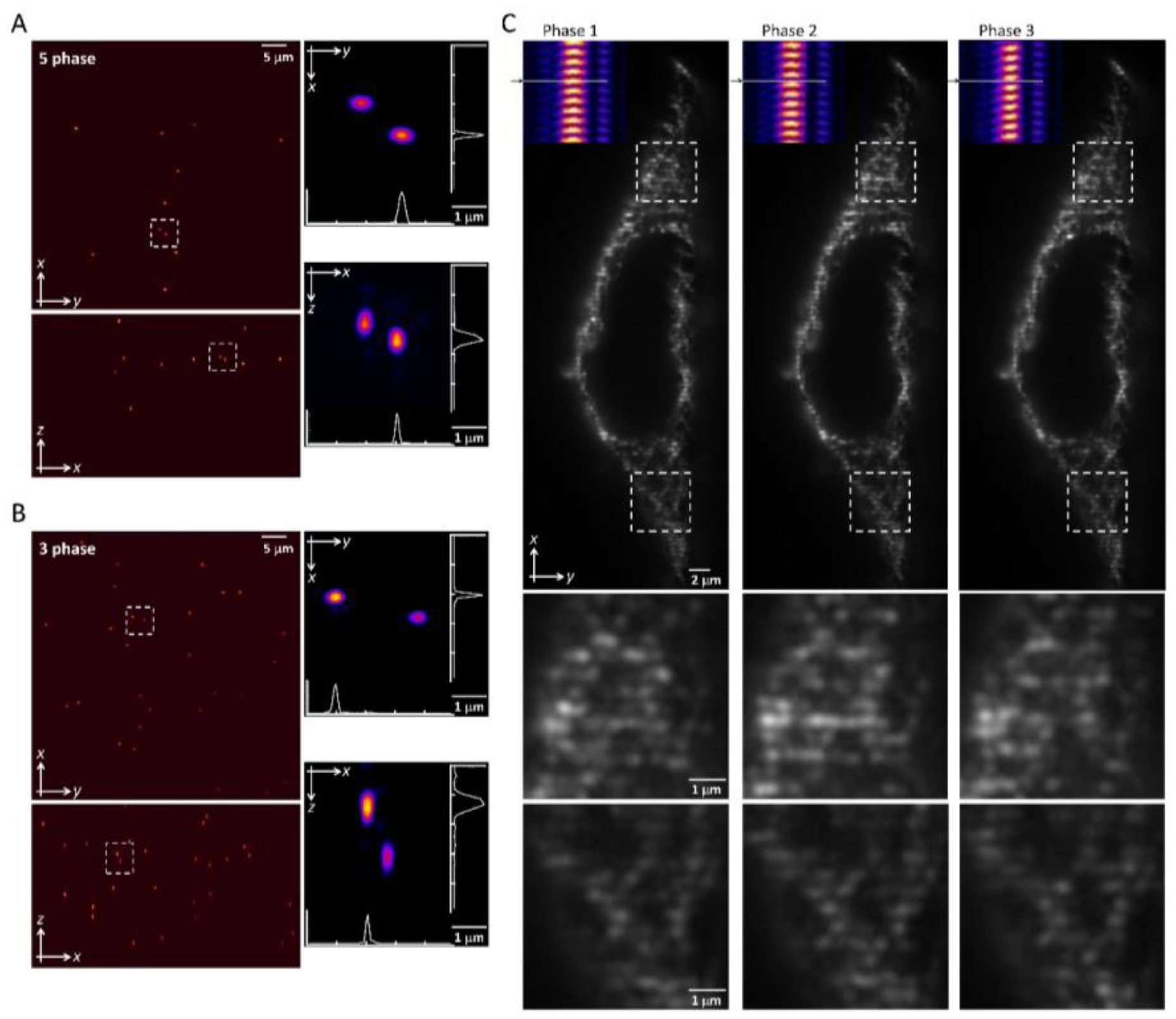
To create the desired lattices, we used an optical path shown in figure 1(B), where a fast switching binary spatial light modular is conjugated to the sample plane of the excitation objective and placed before an aluminum annular mask. The pattern interference from the coherent Bessel beams with optimized confinement to the xy plane was displayed on the SLM, as shown in figure 2(B), resulting in a four-line beam at the BFP of the excitation lens. The square lattice pattern, as shown in the top row of figure 2(C), can be used to perform five phase modulations for the lightsheet 3D-SIM reconstruction. In contrast, by blocking the contribution from the z component at the back pupil of the excitation objective, the relaxed square lattice pattern formed with two-line beam interference at the focal plane. This simplified lattice pattern without much interference from the out-of-plane can be used to perform three-phase modulations for the lightsheet 2D-SIM reconstruction. Apparently, the image speed is improved at 5/3 faster. In terms of spatial resolution, the experimentally reconstructed images of 100 nm green fluorescent beads by 3D-SIM and 2D-SIM are shown separately in figures 3(A) and (B). The 488 nm laser with a 5 ms exposure time for each phase per z plane achieves a spatial resolution of 216 ± 17 nm, 325 ± 10 nm and 287 ± 71 nm in the x, y and z directions, respectively, for 3D-SIM (five-phase); and in the 2D-SIM (three-phase), a resolution of 184 ± 28 nm, 244 ± 48 nm and 384 ± 20 nm, respectively, in x, y and z directions. The 3D-SIM has a better axial resolution over 2D-SIM at the cost of 5/3 more acquisition time. Due to the better signal-to-noise ratio for the three-phase lattice pattern without z components, the SIM reconstruction works better, resulting in a better lateral resolution. Therefore, we chose two-line beam interference to form a relaxed square lattice pattern for three phase modulations, for example, on the cell imaging over 3D, as shown in figure 3(C). The excitation pattern generated by the two-line beam interference and stepped by the galvo mirror is shown in the inset of figure 3(C), and the associated modulations are applied to the sample in the same z plane.

Figure 3. An experimental comparison of the square lattice pattern to perform a five- phase and three-phase lightsheet SIM (A) and (B). A 3D rendering of the reconstruction in the xy (top) and xz (bottom) directions of the 100 nm green fluorescence beads modulated by the five-phase (A) and the three-phase (B) pattern, respectively. The zoom-in of the white dashed boxes is shown on the right and the profile of the bead image is plotted. (C) The represented pictures of the cell sample modulated by three consecutive phases for 2D-SIM reconstruction. The measured excitation profiles shown in the inset applied to the sample plane shows the modulation pattern (zoom-in areas).
Download figure:
Standard image High-resolution imageFixed sample with one color SIM reconstruction
To evaluate the resolution improvement, we imaged red fluorescent beads coated on the coverslip. Figure 4(A) shows the maximum intensity projections (MIPs) in the xy, xz, and yz planes of the image stacks of beads with a dithered square lattice lightsheet, the deconvolution and the 2D-SIM reconstruction. Next, we used MetroloJ—an ImageJ plugin—to measure the resolution [19]. The resolutions in the x, y and z planes are shown in table 1. The lateral resolution of the deconvolved image is close to the theoretical resolution of our detection objective lens, which is  , where 605 denotes the emission wavelength and 1.1 denotes the NA of the objective lens. To compare the lateral resolution improvement, we averaged the numbers in the deconvolution result in the x and y directions as a reference to obtain 303 ± 11 nm, and then used this number to calculate the improvement of the lateral resolution for 2D-SIM. Since the SI pattern is not rotated in LLSM, the lateral resolution is only improved in one direction (x), obtaining 211 ± 10 nm. As a result, the lateral resolution improvement (x) of 2D-SIM is 1.44 ×. The axial resolution basically does not improve in 2D-SIM, as compared to the deconvolved image, since our modified square lattice lightsheet has no periodic pattern in the axial direction. We then imaged a fixed HeLa cell cultured on the coverslip with our modified square lattice pattern. Figure 4(B) shows the MIPs in the xy, xz and yz directions of the image stacks of a fixed cell with the dithered square lattice lightsheet, the deconvolution and the 2D-SIM reconstruction. The microtubules are labeled with Streptavidin Cy3. The 2D-SIM image shows improved resolution and contrast compared to the original and deconvolved images.
Table 1. The quantification of the resolutions of the dithered square lattice lightsheet (2D-SIM, summed), the deconvolution and the 2D-SIM reconstruction. Ten separate beads in figure 4(A) are randomly picked, and then we use MetroloJ—an ImageJ plugin—to measure the full width half maximum (FWHM) of each bead image. Finally, the mean and standard deviation (SD) are given from ten measurements (n = 10) of the individual condition.
| FWHM_x | FWHM_y | FWHM_z | |
|---|---|---|---|
| 2D-SIM, summed |

|

|

|
| 2D-SIM, deconvolved |

|

|

|
| 2D-SIM, reconstructed |

|

|

|

Figure 4. The images of (A) 100 nm red fluorescent beads coated on the coverslip, and (B) the fixed HeLa cell labeled with Cy3 on the microtubule. In (A), the images in the red boxes are magnified in the lower right corner of each panel. The MIPs in the xy, xz, and yz directions of the images in dithered mode, with the deconvolution and SIM reconstructions are shown. The dithered mode image is processed by summing the three or five raw images acquired with 2D-SIM. Deconvolution and SIM reconstruction is performed as described in the SIM reconstruction and deconvolution section.
Download figure:
Standard image High-resolution imageLive sample with two colors
The main advantage of LLSM is the fast acquisition speed. Even with 3D-SIM mode, at 20 ms exposure time per image, five raw images per plane need only 100 ms. This means a 3D-SIM raw image stack of one color with 150 planes needs 15 s. Nevertheless, the acquisition speed can be increased by a factor of 5/3 if the 2D-SIM is applied to the LLSM. With the same exposure time and the same number of planes in a stack, it takes only 9 s to acquire a 2D-SIM raw image stack.
Here we take cell membrane ruffling, which is a leading step in the cell migration process, as an example. We link rapamycin to filamentous actin by using the chemical inducible dimerization (CID) system. Thus, the ruffling is triggered by rapamycin, allowing us to visualize the dynamics of the cytoskeleton and plasma membrane at the beginning of cell migration. Figure 5 shows part of the time lapse of the filamentous actin and plasma membrane in the U2OS cell imaged with 2D-SIM in LLSM. The filamentous actin is labeled with mCherry on the F-tractin binding domain and the plasma membrane is labeled with EYFP fused with the plasma membrane anchor CAAX motif.

Figure 5. Time lapse of the actin (green) and plasma membrane (magenta) in the U2OS cell imaged with 2D-SIM in LLSM. (A) The MIPs in the xy and the zoom-in of the red box. (B) The MIPs in xy, xz and yz of the images in dithered mode, with deconvolution, and SIM reconstructions. The scale bar in (A) is 10 µm.
Download figure:
Standard image High-resolution image
The time interval of the acquisition is about 15.9 s since the exposure time is 20 ms per plane, 121 planes per stack, three stacks per color and two colors are performed. It takes about 30–55 s for the cell to ruffle after the rapamycin is added depending on the protein expression level. We added the rapamycin at 63.3 s (timepoint 5) and continued imaging for a few minutes (40 timepoints of the entire time lapse). As shown in movies s1 and s2 (stacks.iop.org/JPhysD/53/044005/mmedia), the membrane ruffles strongly after it is stimulated. To show the advantages of the better temporal resolution of 2D-SIM, in movie s3 we intentionally delete every other frame in the time lapse, approximately representing half of the temporal resolution as in the case of 3D-SIM. Comparing the full (2D-SIM) and the half (3D-SIM) temporal resolution, the full temporal resolution shows more continuous dynamics variation in the cytoskeleton and membrane ruffling. When presenting the time lapse in a movie with the same speed (frame per second), the 2D-SIM appears in slow motion as compared to the 3D-SIM (movies s2 and s3).
Membrane ruffling is a very dynamic phenomenon. Although it depends on the different cell types, it has been reported that the ruffling rate of an HEKn cell on a non-precoated glass surface can be up to 0.2 ruffles min−1 [16]. Here, we observed an even faster one of about 0.5 ruffles min−1 (figure 5 shows about one ruffle in two minutes) with the U2OS cell, and our fast, super-resolution acquisition shows the ruffling event beautifully. Figure 5(B) demonstrates that the SIM images provide higher resolution and better contrast compared to the deconvolved LLSM images.
Discussion
We regard the formation of a lattice pattern from a different perspective. In the square lattice lightsheet, it is the result of interference from four light beams and can be grouped into an x component and a z component. The original interference from four lightsheets, of course, contains the interaction between these components (figure 2(B)). Nevertheless, the interference in the lateral direction mainly comes from the x component, which means it contributes to the finest pattern in the lateral direction. Therefore, by allowing only the x component light beams to interfere, the lattice pattern exists only in the lateral direction. This means our modified square lattice lightsheet is ideal for 2D-SIM and the acquisition speed is increased by a factor of 1.6, as compared to the previous reported 3D-SIM with a square or hexagonal lattice lightsheet. Moreover, keeping the xz structured lightsheet residing at the focus of the detection objective in the original LLSM-SIM will be critical for the optical alignments and mechanical stabilities. With the compromised spatial resolution and improved imaging speed, the lattice lightsheet with x only patterned could have potential for user-friendly systems, either in a lightsheet SIM or a regular lightsheet for high spatiotemporal resolutions with multicolor detection. This enables fast tracking or the monitoring of subcellular dynamics such as the membrane or cytoskeleton rearrangement inside the cell.
We demonstrated the 2D-SIM in the LLSM in a different way as shown previously [8]. We also demonstrated our method can be used for two or multiple color acquisition. The lateral resolution is unfortunately still anisotropic since the SIM pattern is not rotated. The solution to this would be to use more illumination objective lenses, such as the theta microscope, or adapt the concept of csiLSFM that also combines SIM and LSFM but creates near isotropic resolution [20, 21]. We have demonstrated an acquisition speed up to 15.9 s/stack; the acquisition speed, of course, depends on the exposure time, the number of colors and the number of planes per stack.
The length and the thickness of the lattice lightsheet are basically determined by the outer NA and inner NA of the annulus mask. With our choice of annulus (outer NA = 0.56 and inner NA = 0.47), the lightsheet generated by the red laser excitation is about 23  long and 0.5
  thick in the experimental measurement. Although there is no axially periodic modulation in the 2D-SIM pattern, the 0.5
  thick lightsheet is still thin enough to provide a decent axial resolution. The thin lightsheet helps to decrease the out of focus fluorescence and hence improves the reconstruction accuracy and the image quality in the 2D-SIM mode. The theoretical final resolution of the 2D-SIM can be estimated with equation (1), which is 207 nm as calculated with our experimental parameters, i.e. excitation NA = 0.515, excitation
  = 561 nm, detection NA = 1.1 and detection
  = 605 nm. The best resolution is then 178 nm with excitation
  = 488 nm and detection
  = 515 nm.
where  ,
,  denotes the excitation and detection wavelength, respectively, and
  ,
,  denotes the NA of the excitation beam and the NA of the detection objective lens, respectively. Our experimental result 213 nm (table 1) agrees well with the theoretical value.
In summary, although the 3D-SIM has better axial resolution, the improvement is at best 1.3 × compared to the dithered lattice lightsheet. Practically, in many cases the axial improvement is less than 1.3 ×. In contrast, with our 2D-SIM mode, the increase in the speed is always 1.6 ×. More importantly, due to there being fewer raw images needed for reconstruction, photo-damage and photo-bleaching can be reduced resulting in prolonged imaging acquisition. We simply blocked two line-beams on the Fourier plane of the original square lattice pattern and generated a modified square lattice lightsheet, in which the pattern is only modulated laterally and is ideal for 2D-SIM. We adjust the parameters in our original LLSM control program to enable multiple color illumination. Although we only demonstrate this in 2D-SIM mode, the same concept can also be applied to the original 3D-SIM mode in LLSM. The SIM in LLSM works on both the sample-scan and the objective-scan acquisition. The pattern is still not able to rotate so the lateral resolution is anisotropic. Nevertheless, we demonstrated the acquisition at a sub-second interval per plane with 2D-SIM mode and the image quality improved compared to the dithered mode in LLSM. We hope this report will contribute to the field of bio-imaging when fast acquisition and super-resolution are needed.
Acknowledgment
The microscope control software is licensed by the Howard Hughes Medical Institute, Janelia Research Campus. P C and B-C C acknowledge the support from the Ministry of Science Technology of Taiwan under contract nos. 107-2627-M-001-002, 105-2119-M-001-026-MY2, 106-2627-M-001-006 and 106-2811-M-001-145.