

Abstract
This paper mainly focuses on the fast and efficient design method for plant bioinspired fluidic cellular materials and structures composed of polygonal motor cells. Here we developed a novel structural optimization method with arbitrary polygonal coarse-grid elements based on multiscale finite element frameworks. The fluidic cellular structures are meshed with irregular polygonal coarse-grid elements according to their natural size and the shape of the imbedded motor cells. The multiscale base functions of solid displacement and hydraulic pressure are then constructed to bring the small-scale information of the irregular motor cells to the large-scale simulations on the polygonal coarse-grid elements. On this basis, a new topology optimization method based on the resulting polygonal coarse-grid elements is proposed to determine the optimal distributions or number of motor cells in the smart cellular structures. Three types of optimization problems are solved according to the usages of the fluidic cellular structures. Firstly, the proposed optimization method is utilized to minimize the system compliance of the load-bearing fluidic cellular structures. Second, the method is further extended to design biomimetic compliant actuators of the fluidic cellular materials due to the fact that non-uniform volume expansions of fluid in the cells can induce elastic action. Third, the optimization problem focuses on the weight minimization of the cellular structure under the constraints for the compliance of the whole system. Several representative examples are investigated to validate the effectiveness of the proposed polygon-based topology optimization method of the smart materials.
Export citation and abstract BibTeX RIS
1. Introduction
Recently, fluid/pressure-actuated cellular structures, which are inspired by the nastic movement in higher plants such as the Dionaea muscipula (Venus flytrap) and Onoclea sensibilis (Mimosa), have attracted growing research interest. In a manner similar to the structural characteristics of the higher plant, the bioinspired smart material is commonly composed of fluid-filled isolated closed voids [1]. Investigations have indicated that the smart actuator made of fluidic cellular material can provide a large mechanical force, displacement and hence a high energy density compared with traditional smart materials, such as shape memory materials and piezoelectric materials [2, 3].
The bioinspired fluidic cellular structures present great potential for improving the design, flexibility and functionality of various applications. Many researchers have indicated that the potential applications of fluidic cellular structures range from aircraft applications like droop nose high-lift devices, gapless flaps and shape variable airfoils, to the automotive sector, which would profit from smoothly adjustable seats or rear spoilers. For instance, Vos and Barrett [4] developed pressure-adaptive structures composed of honeycomb cells and pouches that can be pressurized and alter the stiffness of the structure. An application where gross local camber changes of an airfoil were induced by the bioinspired materials was shown in their work. Similarly, Vasista and Tong [5] reported that cellular structure actuated by air pressure tubes can provide forces and eliminate the strict functional separation of actuators and structures, and further, can be used to design a morphing trailing edge structure. Sun et al [6] utilized auxetic honeycomb structures and inflatable tubes to design an actuation system for morphing wingtip applications. Inspired by the foliage articulation of a plant, Barrett and Barrett [2] introduced a lightweight pneumatic control surface actuator. Their investigations illustrated that the bioinspired actuator can provide a higher actuate power and energy densities than nearly all the conventional adaptive materials available today.
In order to perform morphing strategies, the inherently conflicting requirements of low mass, shape adaptability, and high load-carrying capacity should be solved within a complex integrated, multidisciplinary environment. Nature has already illustrated a perfect solution for this challenge. The Venus flytrap, as indicated in figure 1(a), is one of the few plants in which some short timescale actuators can induce large-scale motions. The basic mechanism of the actuators is that a swift drop in turgor pressure at the pulvinar joint due to a change of ion gradation pulls water from the cells [2, 7]. Then, the volume expansion/shrinkage of the cells with different polygonal shapes leads to the macroscopic collapse deformation of the leaves, as shown in figure 1(b). Inspired by this working mechanism, pressure-actuated cellular structures with polygonal motor cells have been developed in the literature. Pagitz et al [8] introduced a morphing leading edge of an aircraft wing assembled with a group of prismatic cells (see figure 1(c)). Their investigations indicated that the motor cells with pentagonal and/or hexagonal cross sections can be tailored for cellular structures to morph into given target shapes. Similarly, pressure-adaptive trailing edges composed of 13 polygonal honeycomb cells are used to alter the aerodynamic coefficients of an airfoil section in Vos and Barrett's work [4] (see figure 1(d)). Vasista and Tong [5, 9] employed a topology optimization method to design the cells' shapes of a pressure-driven morphing aerofoil trailing edge structure. The result indicated that the optimal shapes of the basic unit cells are structures featuring arches, as illustrated in figure 1(d). Luo and Tong [10] further provided a novel analytical formulation based on a statically indeterminate unit cell for pressurized cellular structures. They also presented experimental testing and numerical simulations to demonstrate the feasibility of the pressurized cellular actuator for morphing wing designs [11], as illustrated in figure 1(e). Recently, Gramüller et al [12, 13] proposed an analytical method concerning the physical mechanisms of pressure-actuated cellular structures consisting of unit cells with different edges (see figure 1(f)). Their research concluded that distributed actuation, high control fidelity and a multitude of morphing shapes can be achieved in a cellular arrangement with basic motor cells.
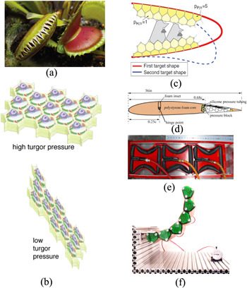
Figure 1. (a) Nastic movement of two different leaves of the Venus flytrap [8]. (b) Lateral contraction, extension and shear of plant cell tissues with variation in hydration [2]. (c) Morphing leading edge of an aircraft wing [8]. (d) Pressure-adaptive flap with 13 pressurized cells [4]. (e) Actuation of the pressurized cellular actuator caused by air pressure [11]. (f) Single row cantilever of pressure-actuated cellular structures [12]. All © IOP Publishing. Reproduced with permission. All rights reserved.
Download figure:
Standard image High-resolution imageOn the other hand, lots of investigations have focused on the design and simulation methods for fluidic cellular structures. Due to the small-scale components of the motor cells, such as the biological membrane in nastic materials [14], the fluidic cellular structures used in real applications commonly consist of a large number of motor cells. In this context, it will be extremely difficult to design and simulate such cellular structures with multiscale features by traditional optimization methods. To overcome these limitations, some methods based on multiscale frameworks were proposed to design such bioinspired adaptive structures. Lv et al [15] proposed a multiscale method to solve the linear behaviors of heterogeneous materials composed of irregular polygonal microstructures. The cellular structures were meshed with polygonal coarse-grid elements, of which the size and shape depended on their natural configuration of imbedded motor cells. The multiscale base functions were then calculated to generate the macroscopic properties of the resulting polygonal coarse-grid elements. Recently, the multiscale method has been extended to simulate the nonlinear behaviors of fluidic cellular structures composed of irregular polygonal unit cells [16]. Since the final calculations were performed on the polygonal coarse-grid elements, these multiscale methods greatly saved the memory cost and CPU time taken to simulate the mechanical behaviors of such heterogeneous structures. Furthermore, these multiscale strategies provide a fundamental framework to develop efficient structural optimization methods to design such complex structures. With this inspiration, Lv et al [17] proposed a multiscale shape and topology optimization method based on multiscale finite element frameworks. The multiscale optimization method could be successfully utilized to solve the problems about the system compliance minimization and compliant mechanism of the fluidic cellular structures. However, this method is limited for those fluid-actuated cellular structures composed of periodically-distributed motor unit cells with quadrilateral shapes. Thus, it will be interesting to develop an optimization method to design these fluidic cellular structures with randomly distributed and unstructured polygonal motor cells.
In the literature, some strategies have been successfully utilized to optimize and design structures based on unstructured elements. Talischi et al [18, 19] proposed an efficient structural topology optimization method including a general finite element routine based on irregular polygonal elements. The complicated target geometries were meshed with convex polygonal elements based on an implicit description of the domain geometry. The method was successfully extended for three-dimensional topology optimization problems based on unstructured polyhedral meshes [20]. The topology optimization of compliance minimization and compliant mechanism problems was investigated by using centroidal Vornonoi tessellation-based polyhedrons. Recently, the tessellations which may be highly skewed, degenerate and non-convex in nature were considered in a topology optimization method to bridge engineering, art, mechanics and architecture [21]. These studies indicated that due to their characteristic geometries, numerical anomalies such as single-node connections and checker boarding can be naturally alleviated with polygons or polyhedrons.
In the present work, we will focus on optimization problems of fluid-actuated cellular structures composed of polygonal motor cells. With the inspiration of the topology optimization method based on unstructured polygonal or polyhedral elements [19, 20] and multiscale methods for fluidic cellular structures [15–17], a novel optimization method using polygons will be developed based on the multiscale finite element framework to optimize the distributions and arrangements of the motor cells in structures. Three classic problems will be extensively studied according to the usage of the smart materials based on the proposed optimization method. First, the study will focus on the system compliance minimization designs of fluidic cellular structures subjected to external forces. Second, these actuators can be regarded as self-actuated compliant mechanisms in which fewer assembly processes and no lubrication were required. Thus, the optimization approach is utilized for a systematic design of the biomimetic compliant actuators of fluidic cellular materials. Finally, the lightweight design problems are synthesized by minimizing the amount of motor cells used in the fluid-actuated cellular structures under the constraints of the compliance of the whole system.
The paper is organized as follows. In section 2, the multiscale finite element framework of fluid-actuated cellular structures with polygonal motor cells is briefly introduced. The polygon-based topology optimization methods to determine the distribution of the motor cells in terms of system compliance minimization, compliant mechanism as well as lightweight designs of the fluidic cellular structure are given in section 3. In section 4, three numerical examples are proposed to evaluate the effectiveness and versatility of the proposed approach. Finally, conclusions are provided in section 5.
2. Polygonal multiscale finite element methods of cellular structures
In this section, the polygonal multiscale finite element method (PMsFEM) of fluid-actuated cellular structures is briefly introduced. Considering the two-dimensional fluidic cellular structure illustrated in figure 2, the structure Ω is composed of polygonal motor cells with arbitrary shapes. Each cell contains a closed inclusion fully filled with incompressible fluid. The basic idea of the PMsFEM is to incorporate the small-scale information into multiscale base functions and capture their effects on the large scale via finite element (FE) computations [15, 16]. In order to apply the PMsFEM to the fluidic cellular structure Ω, two types of mesh grids with different size levels need to be generated. First, the whole structure is meshed with the coarse-grid elements E according to the size and shape of the motor cells imbedded. As the polygonal motor cells are considered, the resulting coarse-grid elements are some irregular polygons. Second, each motor cell continues to be meshed by fine-scale elements (sub-grid elements). Consequently, the mechanical behaviors of fluid-actuated cellular structures can be solved by the PMsFEM with three computational steps, namely the microscale, macroscale and downscaling computations.
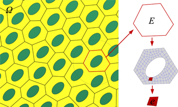
Figure 2. Schematic description of the PMsFEM for a fluidic cellular structure composed of irregular polygonal motor cells.
Download figure:
Standard image High-resolution image2.1. Construction of multiscale base functions for polygonal coarse-grid elements
In the microscale computation step of the PMsFEM, the multiscale base functions for both the solid matrix and fluid phase in the closed inclusions are defined and constructed on sub-grid meshes of the polygonal motor cells. For a polygonal fluidic motor cell with NS sides, the multiscale base functions can be expressed as
where 

 and
and  denote the multiscale displacement base functions of the solid matrix;
  and
and  represent multiscale pressure base functions of the fluid phase;
  and
and  denote the displacements of sub-grid nodes in different directions;
  denotes the fluid pressure inside the inclusion, and
  and
and  denote the displacements of the node i at the polygonal coarse-grid element.
The multiscale base functions defined in equation (1) are numerical values which are constructed on the sub-grid meshes of the unit cells through a FE analysis. The construction method of the multiscale base functions for the polygonal coarse-grid element can be found in detail in the works by Lv et al [15, 16]. In this construction, linear boundary conditions are applied to the sub-grid meshes of the unit cells, and then boundary value problems are performed on the sub-grids via a standard FE analysis. The calculated multiscale base functions are some numerical values which contain small-scale information about the heterogeneous and materials of the polygonal motor cells.
2.2. Equivalent stiffness matrix of the polygonal coarse-grid element
Once the microscale computations are finished for each motor cell, the element stiffness of the polygonal coarse-grid elements can be calculated with the multiscale base functions of the displacement field. Take the polygonal motor cells with Ns sides as an example—the motor cells are meshed with m sub-grid elements. Therefore, the equivalent stiffness matrix  of the polygonal coarse-grid element E can be calculated by

where,  denotes the element stiffness matrix of the sub-grid element e;
  is the transition matrix and it can be written as:

where n is the number of the nodes on the fine-grid e within the unit cell. Once the element stiffness matrices of all the polygonal coarse-grid elements are computed, the mechanical response of the fluidic cellular structure can be easily simulated on the polygonal coarse-grid elements.
2.3. Equivalent loads of the volume expansion of the fluid
The motions of the fluidic cellular structures are caused by the expansion and shrinkage deformation of each motor cell. As illustrated in figure 3, the cell deformation is caused by the volume change of water in the fluid inclusion, which can be regarded as the driving forces. As indicated by various researchers [3, 7, 14], in higher plants the fluid lost or diffused into the cells can be controlled by the biological transport systems in a membrane of the plant cells. The controlled mass transport of charge and fluid across a selectively permeable membrane employing biological processes can achieve bulk deformation of the cells. With this inspiration, some bioinspired driving units, such as the electroosmotic transporting mechanism [22, 23], have been developed in real applications. Recently, some special pressurization devices, such as inflatable rubber tubes [9] and a fluid transfer system with sealing caps [13] have been developed and tested in experiments. Although pressurization systems with a different efficiency can be used to generate the pressure, the motor cells will work in a similar way, i.e. expansion or shrinkage under the pressure generated.
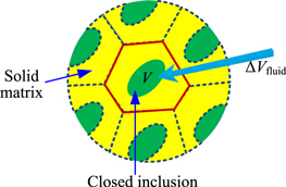
Figure 3. Polygonal fluidic cellular motor cells containing an inclusion fully filled with incompressible fluid.
Download figure:
Standard image High-resolution imageIn this work, in order to model the pressured motor cells, it is assumed that the pressure is generated by the enclosed pressured fluid in the inclusion; further that each inclusion in the motor cells is fully filled with incompressible fluid; moreover, that the inclusion will have no cavitation when the cells are under a tension state. Thus, while the fluid with a volume of  is pumped into the inclusion, the total volume of the fluid inclusion is satisfied as follows:

where V and V0 denote the current and initial volume of the fluid inclusion. With the incompressibility condition, the actuation behaviors of the motor cells can be directly simulated using the standard FEM on the micromechanical models.
An equivalent method needs to be proposed to convert the driving force of the fluidic motor cells into the nodal forces acting on the polygonal coarse-grid elements. It can be found in figure 3 that the driving forces act within the fluid inclusions at the small-scale level, which cannot be directly utilized in the PMsFEM. Zhang et al [24] proposed an equivalent method to transform the volume changes of water inside the motor cells to the equivalent nodal forces on structural coarse-grid elements. In this article, the equivalent method is extended to calculate the equivalent nodal forces of the fluid on the irregular polygonal coarse-grid elements. As indicated in figure 4, the main idea of the equivalent method is that the response of the motor cells under the volume changes of the fluid inside (figure 4(a)) is equal to the response of the polygonal coarse-grid element under equivalent nodal forces  (figure 4(b)). Moreover, the local response of the volume expansion within the unit cell, which is important for the downscaling computation, should not be neglected. More details about the computation can be found in the work by Zhang et al [24].
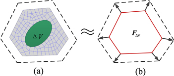
Figure 4. The equivalent method for driving forces caused by the volume change of the fluid inside the motor cells.
Download figure:
Standard image High-resolution imageOnce the equivalent nodal forces are calculated, the actuation capability of the fluidic motor cells can be easily evaluated. It can be observed from the equivalent method introduced above, that the actuation capability of the fluidic motor cells depends on various factors, such as the shape and size of the fluid inclusions, as well as the geometries and physical parameters of the solid matrix in the motor cells. Here we focus on the effect on the physical property parameters, especially the elastic modulus of the solid matrix on the actuation capability of the motor cells. For simplicity, here it is assumed that the solid matrix of the motor cells is homogeneous. Take the motor cell shown in figure 4(a) as an example—the elastic modulus of its solid matrix varies from  to
to  The nodal forces acting on the polygonal coarse-grid element (figure 4(b)) calculated by the equivalent method are plotted in figure 5. It can be observed that the equivalent nodal forces of the motor cells vary linearly with respect to the elastic modulus of the solid matrix. The nodal forces can be expressed as

where  denotes the equivalent nodal force of which a unit volume of incompressible fluid is pumped into the cell, and
  is a linear function about the elastic modulus of the solid matrix in the motor cells.

Figure 5. Equivalent nodal forces varied linearly with respect to the elastic modulus of the solid matrix of the polygonal motor cell.
Download figure:
Standard image High-resolution image3. Polygon-based topology optimization method
In this section, a polygon-based topology optimization method is proposed to determine the arrangements of the motor cells in the fluidic cellular structures to maximize their mechanical performances. As mentioned above, the fluidic cellular structures in real applications are usually composed of a large number of motor cells with irregular polygonal shapes. It is difficult to optimize the distributions and arrangements of the motor cells in the structure using existing standard optimization methods. Alternatively, as the PMsFEM can capture the small-scale information of the polygonal coarse-grid meshes, the structural optimization problems, i.e. the distribution optimization, can be easily performed on these coarse-grid elements using a polygonal-based topology optimization method.
Similar to the standard topology optimization, a proper penalization method needs to be proposed to perform the optimization problems on the polygonal coarse-grid elements. In this paper, a penalization method similar to solid isotropic material with penalization (SIMP) is used to interpolate the macroscale properties of the polygonal coarse-grid elements, i.e. the equivalent stiffness matrix and equivalent nodal forces of the polygonal coarse-grid element. The proposed penalization method is to regularize the original optimization problem with discrete 0 and 1 design variables into a relaxed one with design variables ranging from 0 to 1 [25]. Thus, the nonlinear dependency between the macroscopic properties and the pseudo densities of the motor cells can be established by the interpolation of the penalization method. The macroscopic properties of the motor cells in the fluidic cellular structures can be calculated by combining the equivalent stiffness matrix obtained in equation (2) and the equivalent nodal forces calculated in equation (6) with the penalization method. They can be expressed as


where  and
and  represent the initial equivalent stiffness matrix and equivalent nodal force of the polygonal coarse-grid elements, respectively;
  and
and  denote the practical equivalent stiffness matrix and equivalent nodal force, respectively; p is a penalization factor introduced to ensure black-and-white solutions;
 represents the pseudo density of the polygonal coarse-grid element;
  is a constant
  while
while  is equal to 0.001, and
  is used to avoid numerical singularity of the FE computation on the resulting polygonal coarse-grid elements.
3.1. System compliance minimization of the fluidic cellular structures
The polygon-based topology optimization method firstly focuses on the optimization problems about minimizing the system compliance of the fluidic cellular structures. In this design problem, the fluidic cellular structures are served as load-bearing structures. It is assumed that the motor cells in the structures do not export driving forces. The optimization problem here is to optimize the arrangement of the polygonal motor cells to minimize the system compliance of structures under external loading and boundary conditions. With the upscaling procedure of the PMsFEM, the optimization problem can be converted into finding the macroscopic stiffest configuration of the polygonal coarse-grid elements. Thus, the optimization formulation defined on the polygonal coarse-grid elements can be expressed as follows:
where C is the structural compliance of the fluidic cellular structure, which can be directly calculated on the coarse-grid elements at the macroscopic level;  denotes the design variable; U denotes the displacements matrix of the polygonal coarse-grid elements; K is the global stiffness matrix of the structures;
  is the external load applied on the polygonal coarse-grid mesh; the constant
  is the volume of the design domain;
  is the volume of the coarse-grid element E; f is the prescribed volume fraction and N is the number of the polygonal coarse-grid elements of the cellular structures.
To effectively solve the optimization formulation defined in equation (8), the sensitivity of the object functions with respect to the pseudo densities of polygonal coarse-grid elements should be firstly derived. Similar to those standard topology optimization problems defined on the structural elements, the sensitivity of the objection function  to the design variables of the irregular polygonal coarse-grid element can be easily expressed as:

where  is the pseudo density of the polygonal coarse-grid element E.
3.2. Compliant mechanism design of the fluidic cellular structures
As the fluidic cellular structures can be self-actuated with the motor cells imbedded, it is important to optimize the bioinspired actuator to export displacement in a predefined direction. In this section, the polygon-based topology optimization method is proposed to design the fluid-actuated compliant mechanism. Differing from the system compliance optimization problem, there are no external loads acting on the fluidic cellular structures in this problem. In contrast, the motions of the fluidic cellular structure are induced by internal pressure/volume changes of the fluid inside the motor cells. As introduced in section 2.3, these driving forces can be easily equivalent to the nodal forces at the nodes of the polygonal coarse-grid elements. Therefore, according to standard topology optimization of the compliant mechanism problems, the design of a fluid-actuated compliant mechanism can be naturally performed on polygonal coarse-grid meshes of the structures.
The design problems of the fluid-actuated compliant mechanism can be interpreted as maximizing the displacement in a predefined direction  in response to the equivalent nodal forces of each polygonal coarse-grid element. The optimization formulation of the fluid-actuated complaint mechanism based on the polygonal coarse-grid meshes can be written as follows:
where  is the macroscopic equivalent forces applied on the polygonal coarse-grid element, which is dependent on the pseudo densities of the motor cells. A spring of stiffness
  is applied on the reference point, so the optimal compliant mechanism solved will be dependent on the stiffness of the spring. The irregular polygonal motor cells must be distributed in a structurally efficient way to maximize the work on the output displacement.
The sensitivity of the output displacement with respect to the pseudo densities of the polygonal coarse-grid elements can be derived as:

where λ is the adjoint vector. More details of the derivation of the sensitivity analysis can be found in appendix A below.
3.3. Lightweight design for fluidic cellular structures
For the last problems, the polygon-based topology optimization method is used for the lightweight design of fluidic cellular structures. The aim of the method here is to minimize the number of motor cells distributed in the structures under the constraints for the compliance of the whole system. Based on the PMsFEM, the lightweight design problem can be transformed into the minimum volume problem based on the polygonal coarse-grid elements at the macroscale level. The considered settings may be framed within the following discrete formulation
In the above equation, the structural weight  is computed by multiplying the element density
  for the relevant volume
  over all the N polygonal coarse-grid elements.
  denotes the force vector about the polygonal coarse-grid elements, which are composed of the equivalent loads of the fluid actuation and the direct external forces.
  is the output displacement at a prescribed direction where a spring with stiffness
  is applied;
  is the upper limit of the output displacement. The spring here is used to maintain the structural compliance. The sensitivities for the object function are the same as those for the constraints used in the compliant mechanism problem, while the sensitivities for the constraints are equivalent to those for the object function.
3.4. Numerical implementation
The three topology optimization problems defined above can be effectively carried out based on the sensitivity analyses (see equations (9) and (11)) of many theoretically well-founded optimization algorithms, such as the optimality criteria (OC), aequential linear programming (SLP), sequential quadratic programming (SQP), and the method of moving asymptotes (MMA) [26]. In this research, due to its simple form and high efficiency, the OC is selected to solve the design problems about the system compliance minimization. Furthermore, the compliant mechanism design of the fluidic cellular structures described above has the same form as the system compliance minimization. So the OC is also applied to solve compliant mechanism design problems. However, since the sensitivity of the objective function calculated by equation (11) may take both positive and negative signs, a heuristic modification in the update process should be performed in the OC method for the compliant mechanism design problems [25]. On the other hand, the OC method seems to have some difficulties in solving the lightweight design problems of the fluidic cellular structure proposed here. Instead, the MMA which solves a sequence of linearized sub-problems and uses information from prior iterations to improve the approximation of the design space, is used for the lightweight design problems of fluidic cellular structures. The corresponding computation procedures for all the three optimization problems can be described in a unified way as illustrated in figure 6.
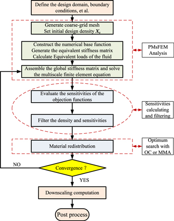
Figure 6. Flowchart for the topology optimization of the adaptive fluid-actuated cellular structures.
Download figure:
Standard image High-resolution imageAs demonstrated in existing works about topology optimization methods based on polygonal elements [19, 20], the polygonal coarse-grid elements with different edges can naturally avoid checkerboard problems. Furthermore, in order to ensure the existence of solutions to the topology optimization problem and avoid mesh-dependency problems, a filtering matrix for the standard polygonal grid elements is introduced for polygonal coarse-grid elements in fluidic cellular structures. For better readability of this article, the filtering matrix of the linear kernel proposed by Talischi et al [19] is briefly introduced here. The filtered field can be written as:

where  is the constant value of the design variable over element
  R is the radius of the linear filter;
  denotes the set of indices of the element
  of which the centroid falls within radius
  of the centroid of element
 denotes the area of the polygonal element k;
  and
and  are the coordinates of the centroids of elements l and k, respectively. The expression can be written in the vector representation as [19]:

where  is the filter matrix and can be stored as a sparse matrix, which is more appropriate for implementation in the computations.
4. Optimization case study
In this section, three examples are given to validate the effectiveness and versatility of the polygon-based optimization methods proposed for fluidic cellular structures. In the first example, square fluidic cellular structures meshed with different types of grids are considered to validate the new optimization method for the compliant mechanism problem. In the second and third examples, a smart wing structure of which the actuation part consists of polygonal motor cells is utilized to validate the proposed optimization method for the system compliance minimization and lightweight design problems. In all the examples, the fluid inside the polygonal motor cells is assumed to be incompressible and no cavity occurs while the closed cells are under a tension state. Moreover, only plane strain problems are considered.
4.1. Compliant mechanism design for a fluidic cellular structure with motor cells
In the first example, three square fluidic cellular structures which are actuated with the imbedded motor cells are considered to validate the proposed optimization method. As illustrated in figure 7, the square structures with a side length of 300 mm consist of 924 triangular, 900 quadrilateral and 900 polygonal motor cells, respectively. Each motor cell contains a circular fluid inclusion with a radius (r = 2.26 mm), and the volume expansion of the fluid in each inclusion is set to  For all the structures, three sides are constrained in all directions, and a spring with a stiffness of
  is attached at the center of the right side of the structure. The Young's modulus and Poisson's ratio of the solid matrix of the motor cells are set to 100 MPa and
  respectively.
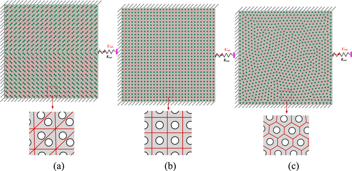
Figure 7. Fluid cellular structures composed of (a) triangular, (b) quadrilateral and (c) polygonal motor cells.
Download figure:
Standard image High-resolution imageIn order to perform the polygon-based optimization method on these structures, the fluidic cellular structures are meshed with different coarse-grid elements according to the size and shape of the motor cell distributed inside. As illustrated in figure 7, the cellular structures composed of triangular and quadrilateral motor cells are directly meshed with standard triangle and quadrilateral coarse-grid elements, respectively. At the same time, the cellular structures with irregular polygonal motor cells are meshed with 900 unstructured polygonal coarse-grid elements. Each coarse-grid element contains a single fluid inclusion. It should be noted that although different types of coarse-grid elements are utilized in the three structures, the codes developed in this article based on the theories proposed can solve these problems in a consistent format.
The final results about the three structures shown in figure 8 were obtained using a linear filter of radius (R = 14 mm) and the SIMP model with continuation performed on the penalty parameter p [19] is used in this example. In order to get the ideal clear topology of the optimal distributions of the motor cells in the structures, the value of p was increased from 4 to 6 using increments of 0.5 in size and a maximum of 150 iterations was allowed for each value of p. It can be observed from figure 8 that the optimization method applied on the three structures with different mesh grids can achieve compliant mechanisms with similar geometries. Among them, the optimization result calculated on the cellular structure meshed with triangular coarse-grid elements (see figure 8(a)) indicates that checkboard problems occur in some local parts of the resulting compliant mechanism. Furthermore, the optimization method can achieve the clearest results on the polygonal coarse-grids (see figure 8(c)), while the compliant mechanism obtained has a smoother boundary than those on structures with standard quadrilateral motor cells (see figure 8(b)).

Figure 8. The optimal distributions of the motor cells in the compliant mechanism designs of the fluidic cellular structure meshed with (a) triangular, (b) quadrilateral and (c) polygonal coarse-grid elements.
Download figure:
Standard image High-resolution image4.2. System compliance minimization problem of a smart wing structure
As introduced above, an important application of the bioinspired fluidic cellular structure is that it can be used to design smart wings for morphing aircraft structures. In this section, the polygon-based optimization method is utilized to design the smart wings structure of fluidic cellular materials. As illustrated in figure 9(a), the Quabeck HQ 3.0/14 R/C sailplane airfoil is considered. The central part of the wing structure is set to the design domain, which is composed of 1800 irregular polygonal motor cells, as shown in figure 9(b). Each motor cell contains a closed inclusion fully filled with incompressible fluid. The fluid inclusions are distributed in the centers of the motor cells. The material properties of the solid matrix in the smart wing are the same as those used in the first example.

Figure 9. (a) HQ 3.5/14 sailplane airfoil; (b) smart wing containing 1800 irregular polygonal motor cells for the system compliance minimization design problems.
Download figure:
Standard image High-resolution imageIn this example, the smart wing structure serves as a load-bearing structure. Further, there is no volume change of fluid inside the motor cells. The purpose here is to illustrate how the distribution of the motor cells affects the mechanical behaviors of smart wing structures. The design domain of the fluidic cellular part in the structure is meshed with 1800 polygonal motor cells according to the shapes of the motor cells. As illustrated in figure 9(b), the left side of the design domain is constrained in both of the two directions, while a uniform distribution load ( in total) is subjected at the tail of the wing structure.
The optimization object here is to minimize the system compliance of the whole structure with a given number of motor cells. The volume function f of the motor cells for this problem is set to 0.4. The linear filter of radius (R = 8 mm) is used in the optimization codes. The penalty parameter p used in the SIMP-like model is increased from 4 to 6 using increments 0.5 in size. The maximum iterations for each value of p are set to 150. The results of the cellular structure with three different sizes of fluid inclusion (r = 0.97 mm, 1.62 mm and 2.11 mm) are illustrated in figure 10. It can be observed that the polygon-based optimization method can successfully solve such a compliance minimization problem. Additionally, clear optimization topologies of the geometries can be found in all smart wing structures composed of motor cells with different shapes. Moreover, it can be found that the sizes of the fluid inclusion in the motor cells can affect the final compliance of the cellular structure, but have little influence on resulting distributions of motor cells in the fluidic cellular structures. The main reason for this is that the stiffness of polygonal motor cells will be weakened simultaneously in all directions by increasing the radius of the fluid inclusion.
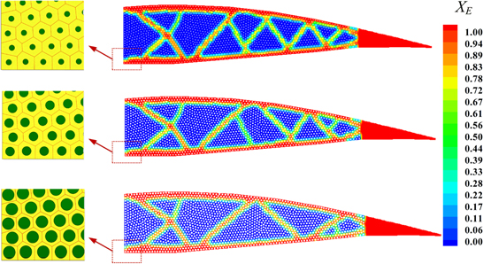
Figure 10. The optimal distributions of the motor cells in the system minimization compliance design of the fluidic cellular structure with different sizes of fluid inclusion in the motor cells.
Download figure:
Standard image High-resolution image4.3. Lightweight design of a smart wing structure
The fluid-actuated cellular structures exhibit multifunctional features, such as self-actuation, shape variability and being lightweight, which makes them useful in the design of morphing flexible aircraft wings. In the last example, we focus on the lightweight design of the smart wing structure to verify the versatility of the polygon-based optimization method proposed in this article. The wing structure of the Quabeck HQ 3.0/14 R/C sailplane airfoil is still considered in this example. The design domain is composed of 1800 polygonal motor cells which separately contain a fluid inclusion. At the same time, different volume increments of the fluid are pumped into inclusions, and their values varied linearly with respect to the vertical positions of the inclusions in the cellular structure. As indicated in figure 11, the left side of the design domain is constrained in both directions. An external uniform force ( in total) is subjected to the top side of the structure, while a spring with a stiffness of
  is attached at the bottom of the tails. The material properties of the solid matrix are the same as those used in the last example detailed above.
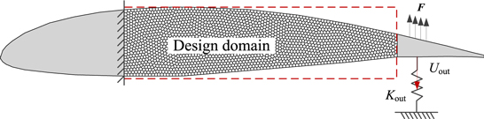
Figure 11. The boundary conditions for the lightweight design of the fluid-actuated cellular structures.
Download figure:
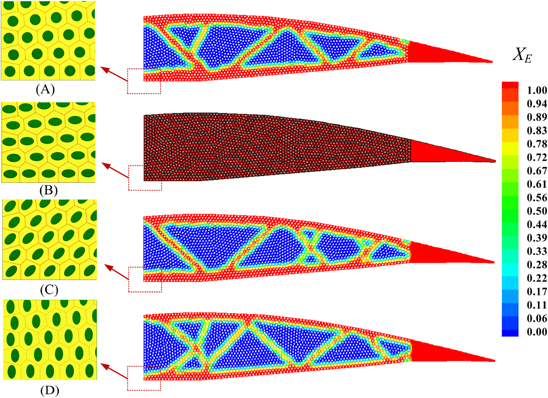
Standard image High-resolution imageThe polygon-based topology optimization method is utilized to minimize the number of motor cells distributed in the smart wing. As introduced above, the lightweight design problem can be converted into a volume minimization problem based on the polygonal coarse-grid mesh, since the PMsFEM is used to bring the small-scale information of the motor cells to the macroscale coarse-grid elements. Here the system compliance constraint is induced to the problems by the upper limit of the output displacement in a prescribed direction  in equation (12). The linear filter of radius in the optimization codes is set to R = 10 mm. The penalty parameter p used in the SIMP-like and the maximum number of iterations are the same as those in the proposed two examples. The final results of the optimization with a different shape of fluid inclusions in the motor cells are given in figure 12. It should be noted that the area of these fluid inclusions is the same in all the motor cells. The results indicated that the polygon-based optimization method can successfully perform the lightweight designs of the fluid-actuated cellular structure. At the same time, the influence of the shape of the motor cell on the final topology of the structure can be also easily captured. It can be found that the weight of the fluidic cellular structure which contains vertical elliptical fluid inclusions (figure 12(d)) can be heavily reduced, while the fluidic cellular structure containing transverse elliptical fluid inclusions (figure 12(b)) cannot lose any weight under these constraints. The main reason for this is that fluidic cells with vertical elliptical inclusions (figure 12(d)) can provide larger driving forces in the x direction than those with transverse elliptical inclusions (figure 12(b)). Therefore, the fluidic cellular structure which contains vertical elliptical fluid inclusions (figure 12(b)) can provide the maximum bending deformation, while the minimum bending deformation is generated by the fluidic cellular structure containing transverse elliptical fluid inclusions (figure 12(d)). These conclusions are consistent with those provided in the works by Lv et al [16].
Figure 12. The optimal distributions of the motor cells (XE = 1/0 denotes solid/void) in the lightweight designs of fluidic cellular structures with (a) circular, (b) horizontal elliptical, (c) inclined elliptical and (vertical elliptical) fluid inclusions in the motor cells.
Download figure:
Standard image High-resolution image
5. Conclusions
A new topology optimization method based on polygonal coarse-grid elements is proposed to determine the optimal distributions and arrangements of motor cells in fluidic cellular structures. Due to the multiscale features of the fluidic cellular structures in practical applications, it is difficult to design such heterogeneous structures with standard methods. In this work, the multiscale finite element framework is utilized for the upscaling computations of fluidic cellular structures. The numerical multiscale base functions are derived to incorporate the small-scale information of the motor cells into macroscopic polygonal coarse-grid elements. On this basis, the optimization problems about the distributions and arrangement of the motor cells in the cellular structures are transformed into topology optimization problems on the polygonal coarse-grid elements.
The topology optimization method based on irregular polygonal elements is utilized to solve the resulting macroscopic design problem on the coarse-grid elements. According to the usages of fluidic cellular structures, three types of design problems are solved by the polygon-based optimization method. In the first problem, this method is synthesized to solve the system compliance minimization of fluidic cellular structures with a fixed number of motor cells. In the second problem, the optimization method is further extended to design biomimetic compliant actuators of fluidic cellular materials, as the non-uniform volume expansions of the fluid in cells can induce elastic actuation. In the last problem, the optimization problem focuses on minimizing the number of motor cells in a cellular structure under the constraints for the compliance of the whole system.
Three representative examples with different cellular structures are utilized to validate the effectiveness of the proposed polygon-based structural optimization method for smart materials. The results indicate that the proposed optimization method can be successfully utilized to perform the design problems of the cellular structures. Moreover, the results indicate that the size of the fluid inclusion in the motor cells will have a big influence on the system compliance of the cellular structure, while the shape of the fluid inclusion can greatly affect the macroscopic distribution and arrangement designs of the fluid-actuated compliant mechanisms. Therefore, it will be interesting to concurrently design fluidic cellular structures by optimizing the arrangement of the motor cells at the macroscale level and the size and shape of the fluid inclusions at the microscale level.
Acknowledgments
The support of the National Natural Science Foundation (11302040, 11402044, and 11232003), the China Postdoctoral Science Foundation (2014T70244), the Fundamental Research Funds for the Central Universities (DUT15RC(4)39), the Ph.D. Programs Foundation of Ministry of Education of China (20130041110050), Science & Technology on Reliability & Environmental Engineering Laboratory (KHZS20143003) and the Enterprise University Research Cooperation Innovation Project of the Aviation Industry Corporation of China (2013) are gratefully acknowledged.
Appendix A: Sensitivity analysis of the compliant mechanism
The sensitivity analysis of the compliant mechanism based on the polygonal coarse-grid elements is similar to those of regular quadrilateral elements [17]. The finite element equation on the polygonal coarse-grid elements under the equivalent loads of the fluid can be expressed as

where  is the global stiffness matrix on the polygonal coarse-grid elements, which depends on the design variable
 is the matrix of the global equivalent loads of the fluid actuation, and U denotes the displacements matrix.
The output displacement  at the prescribed direction where a spring is attached can be rewritten as

In the above equation,  denotes a vector consisting of zero elements except for the position corresponding to the degree of freedom of the output direction where it is set to one,
 ![${{\boldsymbol{L}}}^{{\rm{T}}}={\left[\begin{array}{ccccc}0 & 0 & \cdots & 1 & \begin{array}{ccc}\cdots & 0 & 0\end{array}\end{array}\right]}^{{\rm{T}}}$](https://content.cld.iop.org/journals/0964-1726/25/5/055021/revision1/smsaa1a9dieqn69.gif) .
.
Integrating equation (A1) to equation (A2), the output displacement  can be expressed as
where  is an adjoint vector. The sensitivity of the output displacement
  with respect to design to the design variable
  can be calculated by
In equation (A4), in order to avoid calculating the displacement sensitivity, the terms including  should be set to zero. Thus, the adjoint load problems can be expressed as

Once the adjoint vector  is calculated, the sensitivity equation (A4) can be simplified as
Integrating equations (6B) and (A6), the sensitivity equation of the compliant mechanism problem can be expressed as
