
Abstract
As an alternative to beam-like structures, piezoelectric patch-based energy harvesters attached to thin plates can be readily integrated to plate-like structures in automotive, marine, and aerospace applications, in order to directly exploit structural vibration modes of the host system without mass loading and volumetric occupancy of cantilever attachments. In this paper, a multi-mode equivalent circuit model of a piezo-patch energy harvester integrated to a thin plate is developed and coupled with a standard AC–DC conversion circuit. Equivalent circuit parameters are obtained in two different ways: (1) from the modal analysis solution of a distributed-parameter analytical model and (2) from the finite-element numerical model of the harvester by accounting for two-way coupling. After the analytical modeling effort, multi-mode equivalent circuit representation of the harvester is obtained via electronic circuit simulation software SPICE. Using the SPICE software, electromechanical response of the piezoelectric energy harvester connected to linear and nonlinear circuit elements are computed. Simulation results are validated for the standard AC–AC and AC–DC configurations. For the AC input–AC output problem, voltage frequency response functions are calculated for various resistive loads, and they show excellent agreement with modal analysis-based analytical closed-form solution and with the finite-element model. For the standard ideal AC input–DC output case, a full-wave rectifier and a smoothing capacitor are added to the harvester circuit for conversion of the AC voltage to a stable DC voltage, which is also validated against an existing solution by treating the single-mode plate dynamics as a single-degree-of-freedom system.
Export citation and abstract BibTeX RIS
1. Introduction
Research in the field of vibration-based energy harvesting has received growing attention over the last two decades with the major goal of powering small electronic components and thereby eliminating the need of battery replacement. There exist several transduction mechanisms by means of which vibrational energy can be converted to electrical energy, such as the electrostatic [1, 2], electromagnetic [3, 4], magnetostrictive [5, 6] conversion methods, as well as the use of electroactive polymers [7], electrostrictive polymers [8], and piezoelectric transducers [9, 10]. Among these alternative approaches, piezoelectric energy harvesters have drawn most attention, due to the high power density and ease of application of piezoelectric materials at different geometric scales [11].
The literature on piezoelectric energy harvesting has been mostly concentrated on cantilevered beam harvesters due to their simplicity [10–13]. Analytical distributed parameter modeling [14], assumed-modes modeling [15], Rayleigh–Ritz solutions [16, 17], and electromechanical finite-element numerical models [18, 19] were presented and experimentally validated. Since realistic scenarios of ambient vibrations can be of varying-frequency and random nature, numerous studies explored bandwidth enhancement of the conventional cantilever design. Alternative configurations were proposed by building mechanical band-pass filters with array of beams [20], adding nonlinearities with compressive axial preload configurations [21, 22], attaching movable tip masses [23], introducing magneto-elastic interactions [24, 25], and mechanically stiffening structures [26] for improving the performance of one-dimensional beam-like harvesters.
As an alternative to beam-like structures such as cantilevers, piezoelectric patches can be easily integrated to thin plates to extract vibrational energy of their host structure and convert it into electrical energy. This implementation can be convenient especially for thin structures employed in aerospace, automotive, and marine applications to enable compact and broadband energy harvesting. Integrating piezo-patch energy harvesters to such host plates eliminates the mass loading and volumetric occupancy of base-excited cantilever design. Relatively limited literature has focused on energy harvesting from two-dimensional structures, which is summarized next. De Marqui et al [27] presented an electromechanical finite element model (FEM) for a piezoelectric energy harvester embedded in a cantilever plate, and later on extended this model to airflow excitation problems by electroaeroelastic coupling [28, 29] for energy harvesting from aeroelastic flutter. Rupp et al [30] performed FEM-based topology optimization for cantilever plates and shells to maximize piezoelectric power output. Erturk [31] derived analytical formulation for energy harvesting with piezoelectric patches from surface strain fluctuations of large and high impedance structures through one-way coupling. Harne [32] modeled electroelastic dynamics of a vibrating panel with corrugated piezoelectric spring. Later, he analyzed this corrugated harvester device by attaching it to a panel of a public bus [33]. More recently, Aridogan et al [34] presented analytical closed-form expressions and experimental validations of piezoelectric patch-based energy harvesters structurally integrated to fully clamped plates.
From the electrical domain aspects, in modeling of both cantilever beam-based and plate-like harvesters, usually a simple resistive load is employed to estimate AC power output [34, 35]. However, practical energy harvesters require more complex interface circuits to provide a stable DC signal for storage devices. A standard realistic circuit includes a rectifier bridge followed by a smoothing capacitor as an AC–DC converter [36–38] and further signal regulation can be performed. For instance, Ottman et al [37] suggested using a DC–DC converter after the AC–DC converter to maximize power transfer to the storage device through impedance matching. Synchronized switch harvesting on inductor (SSHI) technique was proposed for increasing the power output in weakly coupled energy harvesters [38–40].
Simulation of piezoelectric energy harvesters with nonlinear circuit elements (e.g. AC–DC converter and/or SSHI circuits) requires implementing equivalent circuit models (ECM) in circuit simulation software (e.g. SPICE) for single/multiple modes of vibration. When equivalent circuits for weakly coupled systems are built, the electromechanical back-coupling can be ignored and the equivalent circuit can be modeled only with the mechanical response being used as an input (i.e. driving voltage or current). However, it is known that [41] ignoring electromechanical back-coupling, results in over estimation of generated power for strongly coupled systems. Therefore, accurate modeling of strongly coupled systems requires inclusion of electromechanical back-coupling in the equivalent circuit. Yang and Tang [19] and Elvin and Elvin [16] developed equivalent circuits including multiple-DOFs and electromechanical back-coupling. Elvin and Elvin [16] obtained equivalent circuit parameters from the Rayleigh–Ritz method while Yang and Tang [19] used the analogy between second-order circuit equation and electromechanically coupled modal equation from the distributed-parameter model of Erturk and Inman [14]. Elvin and Elvin [18] also developed a coupled FEM-SPICE model and Yang and Tang [19] extracted equivalent circuit parameters from FEM results. These studies focused on the conventional cantilever configuration for energy harvesting from base excitation.
As mentioned previously, piezoelectric patch-based energy harvesters attached to thin plates can be readily integrated to plate-like structures in automotive, marine, and aerospace applications, in order to directly exploit structural vibration modes of the host system. This approach eliminates the mass loading and volumetric occupancy of cantilever attachments. In the following, a multi-mode3 ECM of a piezo-patch energy harvester integrated to a thin plate is developed and coupled with a standard AC–DC conversion circuit. Equivalent circuit parameters are obtained from the modal analysis solution of a distributed-parameter analytical model, and alternatively, from the finite-element numerical model of the harvester, by accounting for two-way coupling in both cases. Both AC–AC and AC–DC problems are explored analytically and numerically. Specifically, an analytical single-mode model for the plate is coupled with the AC–DC conversion model of Shu and Lien [36]. Simulations of the analytical model are compared with SPICE simulations.
2. Analytical model
In this section, a brief description of the distributed-parameter electroelastic model of a thin plate with a piezoelectric patch harvester is presented based on the Kirchhoff plate theory [34]. The host plate with all four edges clamped (CCCC) boundary conditions and the structurally integrated piezo-patch harvester are shown in figure 1.
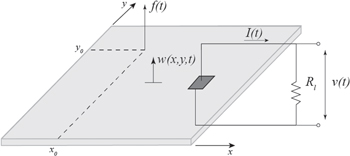
Figure 1. Piezoelectric energy harvesting using a rectangular patch structurally integrated to a thin plate that is under transverse point force excitation.
Download figure:
Standard image High-resolution imageThe host plate is excited by a transverse point force f(t) acting at the position coordinates (x0, y0). The plate is assumed to be sufficiently thin so that the effects of transverse shear deformation and rotary inertia are neglected based on the Kirchhoff plate theory. A piezo-patch with a length of lp and width of wp covers a rectangular region with two corners at (x1, y1) and (x2, y2). The length and the width of the host plate are a and b, respectively. Thicknesses of the host plate and the piezo-patch are hs and hp, respectively. A resistive load (Rl) is considered as an external electrical load connected to the perfectly conductive electrode layers of negligible thickness covering the top and bottom surfaces of the piezo-patch. It is assumed that the piezoelectric volume is much smaller than the host structure so the patch is coupled to the host only electromechanically (with negligible mass and stiffness contribution) and it exhibits piezoelectrically induced moments at the electrode boundaries as the back-coupling effect [42].
The electromechanically coupled equation governing the transverse vibration of the host plate with piezo-patch can be written as

where w(x, y, t) is transverse deflection of the plate. The bending stiffness of the thin plate is  where
where  and
and  are its Young's modulus and Poisson's ratio. The mass density of the plate is ρs while c is the coefficient of viscous damping. The Dirac delta functions are δ(x) and δ(y) along the x and y directions. H(x) and H(y) are the Heaviside functions and
  is the electrode voltage across the external resistive load
  The electromechanical term θ is defined as
  which is the product of the effective plane-stress piezoelectric constant
  and reference distance
  of the center layer of the piezo-patch from the reference surface (i.e. the neutral surface level of the plate in the piezo region) at the location of the patch. The governing equation of the coupled circuit dynamics can be expressed as
where  is the capacitance of the piezo-patch and defined as
  Therefore, equations (1) and (2) constitute the distributed-parameter electroelastic model of piezo-patch harvester in physical coordinates. By conducting the modal analysis procedure for the two-dimensional structure [34], the electromechanically coupled ordinary differential equations of the plate in modal coordinates can be written as

Here,  is the undamped short-circuit natural frequency for the mnth vibration mode and
  is the respective modal damping ratio. Note that the modal forcing in equation (3) is
while the electromechanical coupling term  can be given by
3. Finite-element model
A commercial FEM package (ANSYS) is used for system-level simulations where the voltage output across the electrical load is calculated under the effect of point mechanical excitation. The model of the host structure, the piezo-patch, and the resistive load is shown in figure 2. The host plate is meshed with 20-node structural solid elements (SOLID186) and the piezo-patch is meshed with 20-node coupled field solid elements (SOLID226). The piezo-patch and the host structure are bonded together via CEINTF command in ANSYS, which generates constraint equations relating the nodes at the bonding interfaces. To simulate the highly conductive top and bottom electrode layers of the harvester patch, the electric potential degrees of freedom on the bottom and top surfaces are separately forced to be equipotential in order to have a single voltage output. CIRCU94 piezoelectric circuit element is used for simulating the resistive load connected to the piezo-patch. One end of the piezoelectric circuit element is connected to the top electrode and the other end is connected to the grounded bottom in this model with two-way electromechanical coupling.
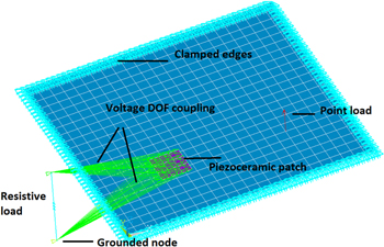
Figure 2. Finite-element model (in ANSYS) used for system-level numerical simulation of a piezo-patch integrated to a fully clamped thin plate and shunted to a resistive load.
Download figure:
Standard image High-resolution image4. Equivalent circuit model
4.1. Equivalent circuit with parameters from the analytical model
Although the analytical distributed-parameter model of the plate is capable of predicting the power output of the system accurately, its practical use is limited with linear circuit components such as a simple resistive load as discussed in section 3. When a resistive load is considered for the AC input–AC output problem, then the analytical distributed-parameter model is very efficient and accurate. However, in the presence of nonlinear circuit components, such as diodes, another approach is required to predict the system response. To this end, an ECM of a piezo-patch harvester integrated to a thin plate is presented and analyzed. This approach is based on the superposition of infinite number of lumped-parameter models which represent the vibration modes. For instance, figure 3 shows the ECM of the piezoelectric energy harvester integrated to a thin plate for the case of simple resistive loading for AC power generation (the case of figure 2). Each vibration mode of the harvester is represented as a second-order circuit connected to a piezo-patch capacitance (CP) and a resistive load (Rl) through an ideal transformer. By applying Kirchhoff's voltage law to the multi-vibration mode circuit and by analogy with equation (3), system parameters of the ECM can be determined. Table 1 gives a summary of the analogy between the analytical distributed-parameter expression and the ECM.
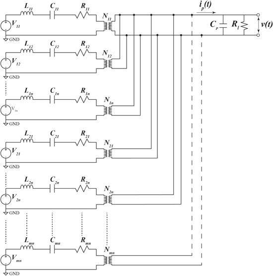
Figure 3. Equivalent circuit representation of a piezo-patch harvester shunted to a resistive load for AC power generation by accounting for multiple vibration modes (a total of  modes).
Download figure:
Standard image High-resolution imageTable 1. Analogy between electrical and mechanical domains of a piezo-patch harvester integrated to a thin plate.
| Equivalent circuit parameters for the mnth vibration mode | Mechanical counterparts |
|---|---|
Voltage source: 
|
Modal point force: 
|
Inductance: 
|
1 |
Resistance: 
|

|
Capacitance: 
|

|
Ideal transformer ratio: 
|

|
Electrical charge: 
|
Modal time response: 
|
Electrical current: 
|

|
Note that, in figure 3, ip(t) is the dependent current source which is the sum of all currents in the branches connected in parallel to piezoelectric capacitance and resistive load. Applying Kirchhoff's current law and by analogy with equation (4), the current flowing to piezoelectric capacitance and the current source can be written as follows:

4.2. Equivalent circuit with parameters from the finite-element model
Parameters of the ECM are extracted from FEM results following the procedure described by Yang and Tang [19] for one-dimensional cantilevers. The first step is to determine the static capacitance  and perform modal analysis to obtain short-circuit natural frequencies
  The second step is to obtain the total admittance of the piezoelectric energy harvester from FEM results with harmonic voltage input. The total admittance is calculated by summing the damped admittance
  with the motion admittance
  :
:

Therefore  can be obtained by excluding
  from the calculated total admittance for each mode which can be directly extracted from FEM results as

Having determined  for each vibration mode,

 and
and  can be identified as:
where 
 and
and  represent the converted form of
 and
and  using the following relations:

Having determined  and
and  the last step is to determine
  using the following equation

where  is the charge response at each natural frequency
  under short-circuit condition.
5. Model validation
In this section, ECM of a fully clamped plate with a perfectly bonded piezo-patch is constructed in SPICE software and simulation results are validated for the standard AC–AC and AC–DC problems. ECM results for AC configuration are validated using the distributed parameter model given by Aridogan et al [34] and also using the system-level FEM results. A single-mode analytical AC–DC model is also obtained following Shu and Lien [36], and compared with numerical simulations. The geometric and material properties of the aluminum plate and the piezo-patch are given in table 2.
Table 2. Geometric and material properties.
| Aluminum | Piezoceramic | |
|---|---|---|
| Length (mm) | 580 | 72.4 |
| Width (mm) | 540 | 72.4 |
| Thickness (mm) | 1.96 | 0.267 |
| Elastic modulus (GPa) | 70 | 69 |
| Mass density (kg m−3) | 2700 | 7800 |
Piezoelectric constant  (C m−2) (C m−2) |
— | −190 |
Permittivity constant  (nF m−1) (nF m−1) |
— | 9.57 |
Damping ratio 
|
0.01 | 0.01 |
5.1. Standard AC–AC problem
In the standard AC input–AC output problem, the energy harvesting circuit is represented by a resistor connected to the piezo-patch as shown in figure 1. Parameters of the multi-mode ECM are identified from both the FE model and the analytical model considering the first nine vibration modes of the plate [34]. Steady-state voltage frequency response functions (FRFs) of the piezo-patch harvester under the effect of a harmonic point force are shown in figures 4 and 5 for various resistive load values (ranging from 100  to 1
to 1  over the frequency range of 0–200 Hz.
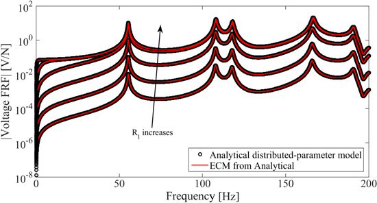
Figure 4. Voltage FRFs of the piezo-patch harvester for a set of resistive loads using the modal analysis-based analytical model and the equivalent circuit model with parameters identified from analytical model.
Download figure:
Standard image High-resolution image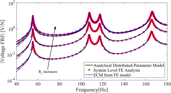
Figure 5. Voltage FRFs of the piezo-patch harvester for a set of resistive loads using the modal analysis-based analytical model, the equivalent circuit model with parameters identified from FEM, and the system-level FEM.
Download figure:
Standard image High-resolution imageFigure 4 shows that voltage output FRFs of the analytical model match perfectly with ECM (simulated in SPICE) for different resistive load cases when parameters are identified from the analytical model. Furthermore, in figure 5, it is observed that voltage amplitudes obtained from the system-level FEM results are in good agreement with those obtained from analytical model with a slight shift in natural frequencies. Slight mismatch is potentially due to ignoring the added mass and stiffness effects of the piezo-patch in the analytical model. The system-level FEM results perfectly agree with the ones obtained from the ECM with parameters identified from the FE model.
Single-mode expressions of the ECM are also compared with the analytical multi-mode solution in the vicinity of the first four modes as shown in figure 6. It is observed that the single-mode results of the ECM are in good agreement with the analytical multi-mode results in the neighborhood of the resonance peaks. Since the neighboring modes are not included, as the excitation frequency deviates from the resonance condition, the single-mode solution fails to be reliable and accurate. Having validated the analytical (modal analysis) results versus numerical (FEM) results through figures 4–6 (note that the analytical model was experimentally validated previously [34]), next the AC–DC conversion problem is explored by adding the standard ideal rectification circuit.
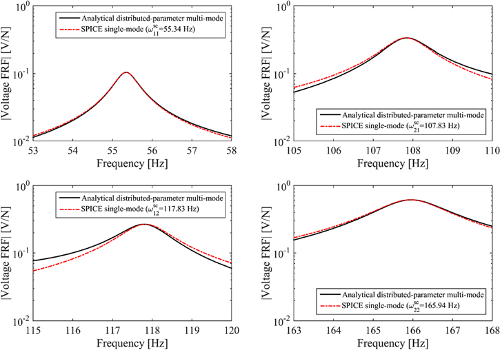
Figure 6. Comparison of analytical multi-mode and SPICE-based single-mode voltage FRFs for the first four vibration modes (Rl = 100 Ω).
Download figure:
Standard image High-resolution image5.2. Standard AC–DC problem
Figure 7 illustrates the standard AC–DC piezoelectric energy harvesting circuit consisting of a full-wave rectifier, a smoothing capacitor, and a resistive load. The lumped-parameter AC–DC model of Shu and Lien considers single mode of the harvester [36] since it deals with the cantilever problem. For that reason, single-mode results of the ECM are compared with the analytical multi-mode solution in the vicinity of the first four modes in a similar way to figure 6. Having validated the single-mode AC input–AC output case (in the resonance neighborhood) as well as the multi-mode cases, the rectified voltage and power output of the ECM of the harvester are to be validated in the standard AC input–DC output problem. To this end, using the lumped-parameters for each vibrational mode, AC–DC harvesting circuit is simulated in SPICE software and validated with the analytical model proposed by Shu and Lien [36]. In their study, the authors developed an analytical formulation of the rectified DC voltage output for the piezoelectric energy harvesters using a lumped-parameter approach. By implementing this model, the steady-state voltage ( for the piezo-patch harvester can be written as:

where the displacement amplitude  is derived in terms of the point forcing amplitude and the system parameters as
Here, the fundamental assumption is that the voltage loss in the diode is negligible as compared to the piezoelectric voltage output so the diode acts like a switch in Shu and Lien's model. In order to generate a stable DC voltage  with negligible ripple, the filter capacitor
  must be large enough so that a constant DC voltage output can be achieved [43]. Ideal transformer and diodes are used in the ECM simulations in SPICE to compare numerical results with Shu and Lien's analytical model [36]. Analysis of the harvesting circuit is performed for each vibration mode in SPICE software. By conducting time-domain analysis for the harvester circuit, steady-state voltage values are extracted for various values of the resistive loads. Figures 8 and 9 present the SPICE simulation results for the resonant DC voltage and power outputs and compare the results with Shu and Lien's analytical model [36] for a wide range of resistive loads. The results are in excellent agreement when the assumptions in the SPICE model agree with the analytical approach. Clearly the ECM can handle more complex circuits, such as non-ideal diode behavior and other losses, as well as switching and DC–DC regulation circuits, when used in conjunction with SPICE.
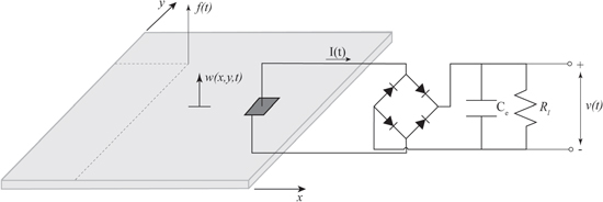
Figure 7. Piezo-patch energy harvester connected to a standard AC–DC conversion circuit: a full-wave rectifier, a smoothing capacitor, and a resistive load.
Download figure:
Standard image High-resolution image
Figure 8. Rectified DC voltage output from Shu and Lien's analytical model and from the equivalent circuit model.
Download figure:
Standard image High-resolution image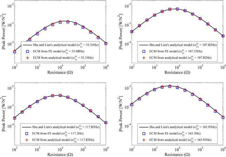
Figure 9. DC power output from Shu and Lien's analytical model and from the equivalent circuit model.
Download figure:
Standard image High-resolution image
6. Conclusions
Piezoelectric patch-based energy harvesters attached to thin plates can be integrated to two-dimensional thin structures in automotive, marine, and aerospace applications, in order to directly exploit structural vibration modes of the host system. Based on this approach, mass loading and volumetric occupancy of base excited cantilever attachments can be eliminated. In this work, an ECM of a piezoelectric patch-based harvester attached on a thin plate was developed and validated for the standard AC–AC and ideal AC–DC circuit configurations. The equivalent circuit parameters considering multiple vibration modes of the harvester were identified from the analytical and FEMs. Then, using these system parameters, simulations were conducted in SPICE software. The simulation results of voltage FRFs in the AC–AC configuration were presented for a wide range of resistive load cases and verified against both the analytical distributed-parameter and system-level FEMs. It was shown that ECM accurately represents the coupled electromechanical behavior of the harvester. Equivalent circuit single-mode representation was also verified with the analytical multi-mode solution in the vicinity of vibration modes. Then, the single-mode ECM was connected to a full-wave rectifier, a smoothing capacitor, and a resistive load as a standard AC–DC conversion circuit. Steady-state electrical responses were investigated for the first two modes of the harvester. Resonant modal (i.e. single-mode) DC voltage and power outputs for different resistive loads were computed and validated against the existing analytical single-degree-of-freedom model proposed by Shu and Lien [36]. The multi-mode ECM developed in this study enables exploring the harvesting performance of the piezoelectric patch-based harvesters attached to thin plates with any linear and nonlinear electrical components, including non-ideal circuit components as well as DC–DC regulation circuits when used along with software such as SPICE for system-level design and optimization.
Acknowledgments
The authors acknowledge support from the Koc University TUPRAS Energy Center (KUTEM).
Footnotes
- 3
The term 'multi-mode' in the present context refers to including multiple vibration modes of the host structure plate.