
Abstract
This paper introduces an advanced vision-based system for dynamic real-time displacement measurement of high-rise buildings using a partitioning approach. The partitioning method is based on the successive estimation of relative displacements and rotational angles at several floors using a multiple vision-based displacement measurement system. In this study, two significant improvements were made to realize the partitioning method: (1) time synchronization, (2) real-time dynamic measurement. Displacement data and time synchronization information are wirelessly transferred via a network using the TCP/IP protocol. The time synchronization process is periodically conducted by the master system to guarantee the system time at the master and slave systems are synchronized. The slave system is capable of dynamic real-time measurement and it is possible to economically expand measurement points at slave levels using commercial devices. To verify the accuracy and feasibility of the synchronized multi-point vision-based system and partitioning approach, many laboratory tests were carried out on a three-story steel frame model. Furthermore, several tests were conducted on a five-story steel frame tower equipped with a hybrid mass damper to experimentally confirm the effectiveness of the proposed system.
Export citation and abstract BibTeX RIS
1. Introduction
Civil engineering structures such as bridges and buildings endure various external loads during their life cycle. Structural health monitoring is becoming an important topic to ensure that structures maintain their structural performance. Displacement is one of the most important physical quantities to be monitored in the framework of structural health monitoring. Several techniques currently available for measuring the displacement of structures can be divided into contact-type methods such as a linear variable differential transformer (LVDT) and non-contact-type methods such as the accelerometer-based technique [1], the global positioning system (GPS) [2–5], the laser Doppler vibrometer (LDV) [6], and vision-based system [7–11]. However, contact-type methods may not be feasible for civil engineering applications since they require that stable reference points be fixed and that sensors be installed in suitable places in large-scale infrastructures such as high-rise buildings and long-span bridges [12]. Since most non-contact-type methods, except for the accelerometer-based technique, have a high level of resolution, their implementation is limited by high cost. The acceleration-based technique is relatively easy to obtain a displacement by the double integration of acceleration data, but the result may not be stable because of bias in low-frequency content [12].
In reality, directly obtaining the displacement of large-scale structures such as long-span bridges and high-rise buildings from hundred of meters away is virtually impossible, and at best challenging, because of limitations of optical equipment such as cameras and optical lenses. In 2010, Park et al [12] presented a promising partitioning approach for measuring the deflection of large-scale structures. Some static laboratory tests were conducted to verify the accuracy and feasibility of the partitioning approach on a steel column structure with an error of less than 1.0%. However, since they did not conduct any dynamic measurement tests, the efficiency and feasibility of dynamic measurements are still under scrutiny.
The main objective of this study is to introduce an advanced vision-based system for dynamic real-time displacement measurement of high-rise buildings using the partitioning approach. Compared to the previous vision-based displacement measurement systems, the proposed system has the following significant advantages: (1) it can simultaneously support two camcorders at the subsystem level for dynamic real-time displacement measurement, (2) time synchronization and data connection of each subsystem are transferred via a network using the TCP/IP protocol, (3) the dynamic displacement of high-rise structures can be tracked from far distances using a partitioning method, and (4) the dynamic rotational angle can be measured with high resolution. To verify the efficiency, stability, and accuracy of this system, we carried out many tests on a three-story steel frame model and a five-story steel frame tower with a hybrid mass damper (HMD).
This paper is organized as follows. Section 2 briefly reviews the partitioning approach, section 3 presents the results of laboratory verifications, section 4 presents the tests on a five-story steel frame tower, and section 5 concludes this work.
2. Partitioning method
In 2010, Park et al [12] introduced the partitioning method for measuring the actual displacement at the top floor of a high-rise building. For the ideal shear building model, it is possible to divide large-scale structures into several segments, mounting the vision-based measurement system on each segment, and then obtain displacement on the top floor by simply adding the relative displacements at each segment. In real deformation, however, bending behavior causes the structure to rotate and contributes to the total deformation. To obtain the total deformation, rotational angles should be measured. Rotational angles can be obtained using an inclinometer incorporated on each set of cameras. However, the use of inclinometers complicates the system and raises its cost because of compatibility with the current vision-based system and the cost proportional to the performance of the device. Furthermore, the commercially available inclinometer has limited dynamic performance if it is used to measure very accurate rotational angles of civil-structures. Therefore, to measure the rotational angle accurately and cost-effectively without an inclinometer, Park et al [12] employed additional cameras that could produce redundant observations.
Figure 1 was re-drawn to briefly explain the partitioning method proposed by Park et al [12]. The initial assumption is that Cam01 and Cam02 are placed at the base of structure where there is no displacement and rotation. Cam01 and Cam02 will track targets P1 and P2, respectively. Similarly, a pair of cameras, Cam12 and Cam13, will aim at targets P2 and P3, and so on. Displacement δ(n−2)(n−1) is the deflection obtained by the camera at the (n − 2)th row tracking target Pn−1, and Camij means the camera which is installed on the ith row aiming target Pj. Initially, displacements δ1 and δ2 are measured by Cam01 and Cam02. Furthermore, displacements δ12 and δ13 are produced by Cam12 and Cam13 aiming at targets P2 and P3, respectively. The slope change (θn−2) and horizontal displacement (δn) are summarized in figure 1.
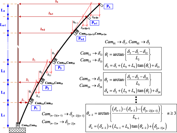
Figure 1. Partitioning method proposed by Park et al [12].
Download figure:
Standard imagePark et al [12] verified the basic scheme of the partitioning approach through static laboratory tests on a steel column. While this study introduces the complete system deploying partitioning method which is applicable to tracking motions of large-scale structures from a far distance using commercial equipment, there remain two key issues for the partitioning method to be realized: (1) time synchronization between master and slave systems and (2) real-time dynamic measurement.
- Time synchronization. Time synchronization between master and slave PCs is one of the key issues to be resolved to get the final result based on the equations in figure 1. All the raw data should be simultaneously measured and they should be transmitted to the master PC to calculate the rotational angle in between and the displacement at the far location. Time synchronization is a critical piece of infrastructure in any distributed system, but wireless sensor networks make particularly extensive use of synchronized time [13]. In the proposed system, without time synchronization, it is usually impossible to identify where the receiving data from the subsystems should be in the time history, thus the wrong final results will be produced. To maintain an acceptable time lag of less than 3 ms, time synchronization should be carried out every minute. In this study, the whole system is synchronized via computers under the TCP/IP protocol, which is easy to implement and popular in the area of wireless sensor networks.
- Real-time dynamic measurement. Park et al [12] did not conduct any dynamic measurements, so the efficiency and feasibility of dynamic measurements are still under scrutiny. Since most of the civil infrastructures have major frequency contents less than 10 Hz, the proposed system can successfully track the dynamic displacement of structures using commercial cameras with 30 frames per second (fps). Also, the proposed system takes less than 1/30 s for the data processing including image capture, image processing, and wireless data transmission. This makes the proposed system applicable to real-time operation. The results show very good agreement with the direct measurement result proposed by Lee and Shinozuka [9].
3. Laboratory verifications
Laboratory tests consisted of two types: the first focused on the accuracy of the synchronized multi-point vision-based system and the second assessed the feasibility of the vision-based system using the partitioning approach on a three-story steel frame model in static and dynamic cases.
3.1. Synchronized vision-based displacement test
A detailed flowchart of the advanced vision-based system for dynamic real-time displacement measurement is shown in figure 2. To measure the structural displacement, target panels were attached on a desired location of a building, and then camcorders captured the images of the target panels from a remote distance, regarded as a fixed reference point. The target panels could be marked directly on the building without using the panels. The images were streamed into the PC via frame grabbers, and the software calculated the displacement of the target by applying image-processing techniques with pre-measured calibration parameters. The actual structural displacement can be calculated using a trigonometric transformation matrix and scaling factors. The transformation matrix is calculated from the positions of the detected white spots on the target and scaling factors relate the pixel information to the actual geometric information based on the predetermined geometry of the target. More details were explained by Lee and Shinozuka [9].
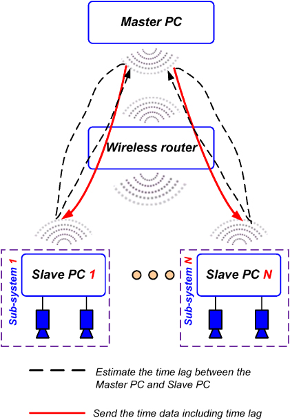
Figure 2. Vision-based displacement measurement system.
Download figure:
Standard imageThe calibration process, which has to be periodically carried out to maintain time synchronization between the master PC and the slave PCs, is illustrated in figure 2. The master PC adjusted the local time of the subsystem PCs by measuring the lag time of the wireless communication. Initially, the master PC sends the dummy time data that has the same data size to all the slave PCs. When the data reaches the slave PCs, they simply return the received dummy data to the master PC immediately. Next, the master PC calculates the time delay between all subsystems by measuring the time gap between the sending and receiving times. Then the master PC sends the time obtained from its own internal clock, including the time delay to each subsystem. Finally, the slave PCs adjust the internal clock according to the received time data from the master PC. To maintain time synchronization between the master PC and slave PCs, the software calibrated the time every 60 s.
The performance as well as the stability of this vision-based system was evaluated using the shaking table test, shown in figure 3. The results of this test were compared with those from the linear variable differential transformer (LVDT). The details of hardware components are given in table 1; a Lenovo X201 tablet was used as the master PC. Two subsystems simultaneously tracked the same target panel at a distance of 15 m. All the subsystems were connected to the master PC via a wireless LAN access point placed at a distance of 10 m from all the PCs. The distance between the systems was determined considering the performance of telescopic lenses and camcorders.
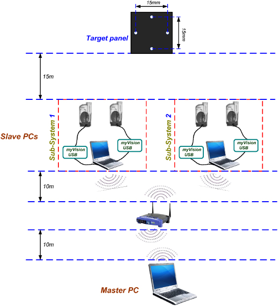
Figure 3. Testing setup.
Download figure:
Standard imageTable 1. List of hardware components.
| No. | Device name | Quantity |
|---|---|---|
| 1 | Lenovo R61, Intel Core Duo 2.4 MHz, 160 GB of HDD, 2 GB of RAM | 1 |
| 2 | Acer Aspire 5580, Intel Core 2-Duo 1.66 MHz, 160 GB of HDD, 3 GB of RAM | 1 |
| 3 | Lenovo X201 Tablet, Intel Core i7-640LM 2.13 MHz, 320 GB of HDD, 4 GB of RAM | 1 |
| 4 | Camcorder JVC GZ-MS120 | 3 |
| 5 | Camcorder PV-GS35 | 1 |
| 6 | Telescopic lens, 40 × optical zooming capability | 4 |
| 7 | Frame grabber myVision USB [14] | 4 |
| 8 | Wireless router complying with 802.11 g | 1 |
The frame size was 640 pixels × 480 pixels, and the target size was 15 mm in the vertical and horizontal directions. The camera was placed at 15 m from the target. The number of pixels between the uppermost white spot and the lowermost white spot was 284. Thus the physical resolution was 0.053 mm/pixel. The residuals (errors) between the results obtained by the proposed system and the conventional sensor were found to be less than 2% considering the maximum displacement of 3 mm. In reality, the maximum relative displacement between two adjacent floors (inter-story drift) can be very small. However, the maximum relative displacement can reach up to several millimeters when we install the two consecutive subsystems at a reasonable distance. Considering the resolution of the proposed system, the displacement and rotational angle at the camera location can be measured very accurately. The software, including the time synchronization algorithm, was installed on both the master PC and the slave PCs.
Figure 4 compares the displacements measured from the LVDT sensors with those obtained from the system with the periodical time synchronization process. With sinusoidal excitations of 1 and 4 Hz, the displacements obtained from the system were in strong agreement with the measurements from LVDT, and the variation in the maximum values between the LVDT outputs and the system outputs was less than 2.0%. The proposed vision-based system can handle two cameras with 30 fps in real time, so it can capture the motion with a vibration frequency of less than 15 Hz (Nyquist frequency). High-rise buildings usually have major frequency contents of less than several hertz [9, 10], thus the proposed system can be applicable to measuring the displacement of high-rise buildings.
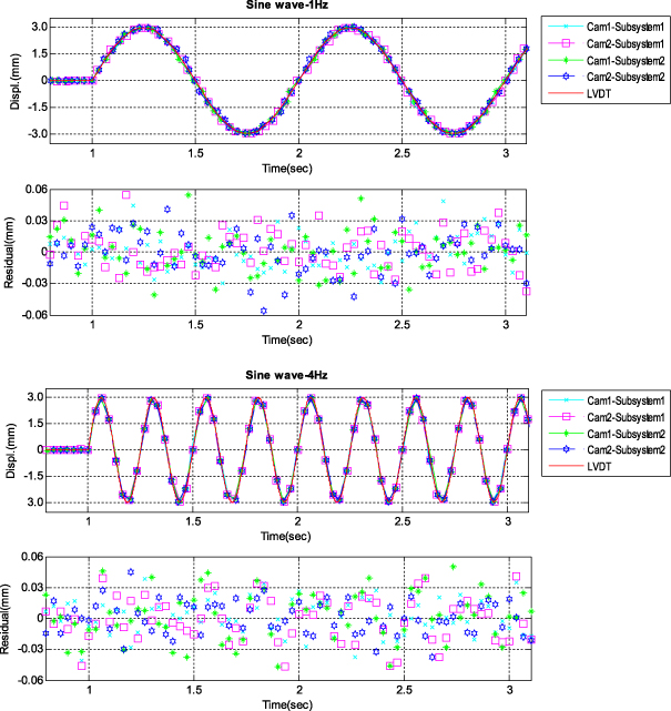
Figure 4. Shaking table test results.
Download figure:
Standard image3.2. Testing on a three-story steel frame using synchronized vision-based system and partitioning approach
This test is conducted to verify the feasibility of combining the synchronized vision-based system with the partitioning approach for a three-story steel model, and the typical hardware specifications are given in table 1.
The software, including the time synchronization algorithm, was installed on both the master PC and the slave PCs. The final displacement at the top of the structure was determined using the partitioning approach at the master PC. The structure specifications, the camera, and target installation are described in figure 5.
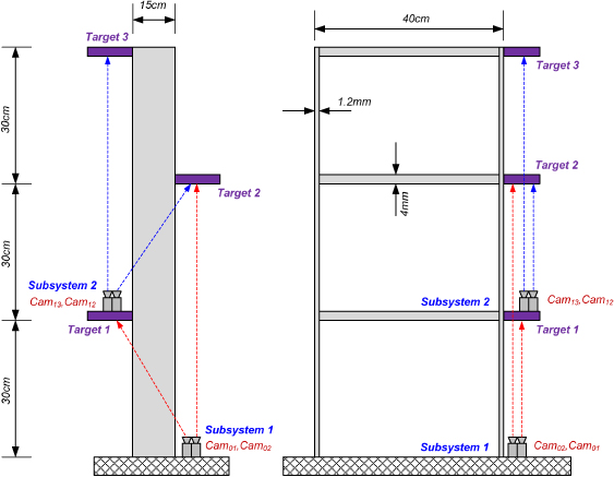
Figure 5. Camera and target location.
Download figure:
Standard imageThe test is conducted by applying a series of known artificial displacements at the top of the structure, and the assumed structural deflection is depicted in figure 6. Four cameras capture these deflections at targets 1, 2, and 3; then all the information is wirelessly sent to the master PC to calculate the rotational angle at target 1 (θ1) and the top displacement (δ3). The target size used in this test is 10 mm × 10 mm. The absolute deflections at targets 1 (δ1) and 2 (δ2) are obtained using Cam01 and Cam02. Similarly, the relative deflections δ12 and δ13 are found by Cam12 and Cam13, respectively. Finally, substituting all the measured values (δ1;δ2,δ12;δ13) into the equations in figure 1 yields the rotational angle at target 1 (θ1) and the top displacement (δ3). The static test results are summarized in table 2. The average of the error (difference) is 0.58%, so the outputs of this system (δ3) show very good agreement with the known displacements, with a maximum error of less than 1.0% in all the test cases. In the dynamic test, a vision-based measurement system proposed by Lee and Shinozuka [9] was utilized to directly capture the top displacement (δ3). Compared with direct measurement, the outputs of the proposed system show very good agreement with the variation in the maximum values was less than 2.0%, as shown in figure 7.
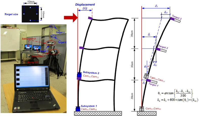
Figure 6. Experimental setup.
Download figure:
Standard image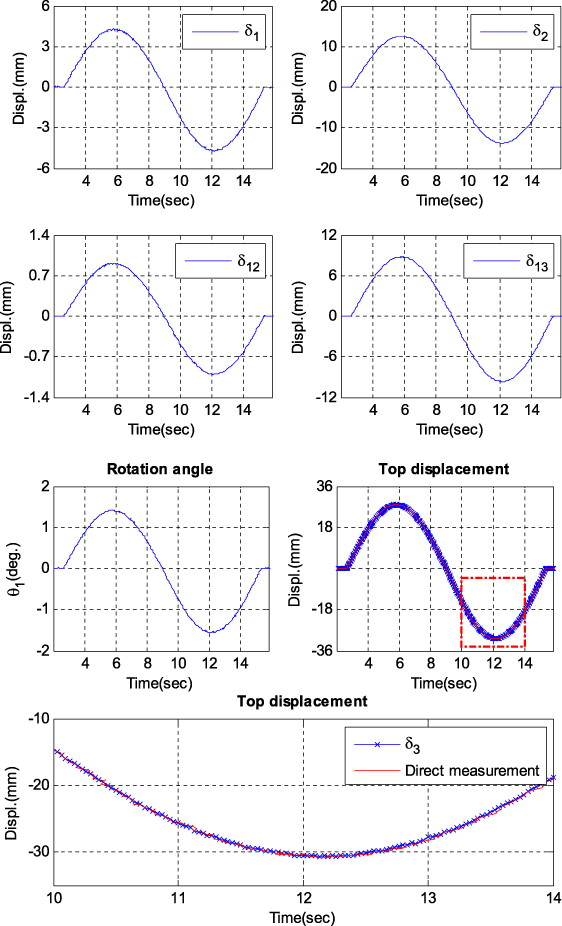
Figure 7. Dynamic test results.
Download figure:
Standard imageTable 2. Static test results.
| Test no. | δ1 (mm) | δ2 (mm) | δ12 (mm) | δ13 (mm) | θ1 (deg) | δ3 (mm) | Exact displacement (mm) | Difference (%) |
|---|---|---|---|---|---|---|---|---|
| 1 | 4.33 | 13.51 | 0.96 | 9.41 | 1.57 | 30.19 | 30.00 | 0.62 |
| 2 | 5.34 | 15.93 | 1.32 | 16.34 | 1.77 | 40.22 | 40.00 | 0.55 |
| 3 | 6.33 | 18.12 | 1.53 | 22.77 | 1.96 | 49.63 | 50.00 | 0.74 |
| 4 | 7.02 | 20.96 | 1.83 | 29.03 | 2.31 | 60.27 | 60.00 | 0.45 |
| 5 | 7.95 | 23.63 | 2.11 | 34.52 | 2.59 | 69.61 | 70.00 | 0.56 |
4. Testing on the five-story steel frame tower
4.1. Testing setup
The proposed system was verified through a full-scale implementation on a five-story steel frame tower with an HMD inside. An HMD can be used as a damping device, but in this study it was utilized as an exciter controlled by a processing unit. Figure 8 shows the test structure and experimental setup. The cameras were divided into two groups: Subsystem 1 and Subsystem 2. Subsystem 1 was located at the ground floor, and Subsystem 2 was installed at the second floor.
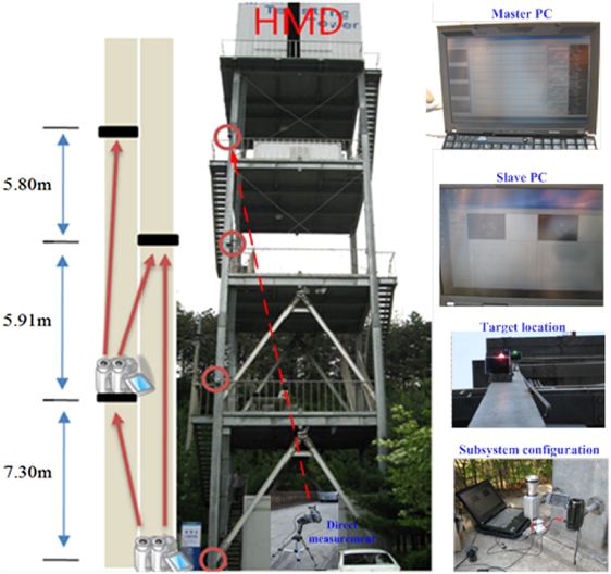
Figure 8. Experimental setup of the field test.
Download figure:
Standard imageThe hardware components are given in table 1, and the Lenovo X201 tablet was used as the master PC. The absolute displacements of the targets on the second and third floors, and the relative displacements of the targets on the third and fourth floors were obtained by Cam2-Subsystem1, Cam1-Subsystem1, Cam2-Subsystem2, and Cam1-Subsystem2, respectively. To verify the proposed system, we used an HMD to excite the test structure by applying two methods of excitation: sinusoidal and random excitation. To suggest reference data, a single-point measurement system (introduced by Lee and Shinozuka [9]) was installed at the tower base, allowing for direct observation of the target on the fourth floor.
4.2. Results and discussion
Figures 9 and 10 show the displacement data measured by four cameras, the estimated rotational angle, and the results of the comparison between the reference data and the displacements obtained by the proposed system. In addition, the maximum displacements of Cam1-Subsystem1 and Cam1-Subsystem2 were almost twice as large as those of Cam2-Subsystem1 and Cam2-Subsystem2. Furthermore, the maximum rotational angles were less than 0.045° and 0.015° under sinusoidal and random excitations, respectively. The estimated rotational angle exhibited very good dynamic resolution. The calculated displacements at the fourth floor closely matched those of the direct measured data, and the variation in the maximum values was less than 2.0%. From these results, it is concluded that the proposed vision-based system can successfully measure the dynamic horizontal displacement of a high-rise building.
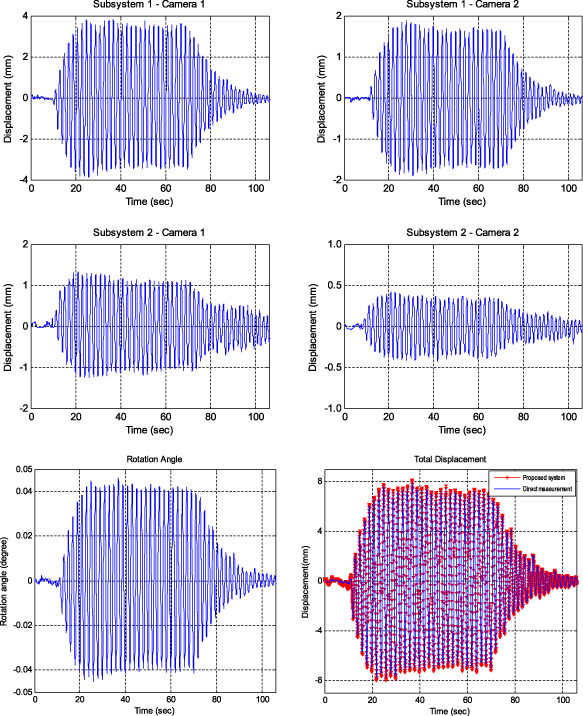
Figure 9. Measured and estimated data under sinusoidal excitation.
Download figure:
Standard image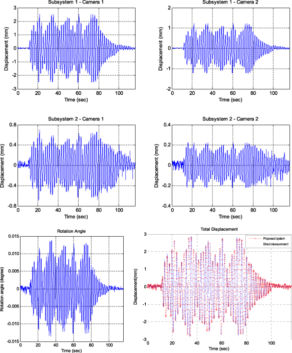
Figure 10. Measured and estimated data under random excitation.
Download figure:
Standard image5. Conclusions
The proposed vision-based system using a partitioning method can overcome limitations pertaining to the range of visibility, which is the innate drawback of most vision devices, by means of successive estimation of relative displacements and rotational angles at several floors. In addition, the proposed measurement system can remotely track the structural displacement in a cost-effective manner by using the partitioning method, inexpensive optical equipment, TCP-IP based time synchronization, and wireless data transmission. The feasibility of the proposed system has been experimentally verified by laboratory tests on a three-story steel frame model with errors of less than 2.0% in all cases, and by tests on the five-story steel frame tower with an HMD. From the experimental results of the five-story steel frame tower, we observed that the proposed system is effective for measuring the horizontal displacements of a tall building while accurately estimating the rotational angle in between. The errors of the proposed system and the directly measured displacements were found to be less than 2.0%. Furthermore, the proposed system can support two cameras at the subsystem level for real-time displacement measurement and involves a time synchronization process and data connection that can be wirelessly transferred via a network using the TCP/IP protocol. Finally, the proposed vision-based system provides the following benefits: (1) it conducts long-distance, dynamic measurement with high resolution; (2) it is cost-effective; (3) it performs real-time synchronized measurement; (4) it performs dynamic rotational angle measurement with high resolution; (5) it can economically and easily expand measurement points; (6) it contains a user-friendly software interface; and (7) it is easy to install and operate.
Acknowledgments
This work was supported by the Korea Ministry of Land, Transportation Maritime Affairs (MLTM) through Core Research Project 4 of the Super Long Span Bridge R&D Center (08 CTIP-E01). This work was also funded by the research project 'Development of SONAR-based Smart Underwater Inspection System for Bridge Hazard Prevention (11CTIP-D03)'. The authors sincerely appreciate their financial support.