

Abstract
The faceting of In2O3(0 0 1), (0 1 1), and (1 1 1) grown by plasma-assisted molecular beam epitaxy on yttria-stabilised zirconia was investigated under different growth conditions—conventionally used oxygen-rich growth conditions with and without heavy Sn-doping, and indium-rich growth conditions—by in situ reflection high-energy electron diffraction, scanning electron microscopy, x-ray diffraction, and atomic force microscopy. In a simple thermodynamic model that considers surface free energy only, the observed faceting is compared to recent theoretical predictions of the surface tension (also termed surface free energy) anisotropy and the related equilibrium crystal shape derived from a Wulff construction. These predictions and our comparison include the variation with growth-condition-dependent oxygen chemical potential. Our results demonstrate how the experimentally changed oxygen chemical potential controls the faceting or island shape of In2O3 by changing the surface tension anisotropy. While the experimental results largely agree with the theoretically derived surface tension anisotropy, they strongly suggest a lower relative surface tension of the (0 0 1) surface at lower oxygen chemical potential (In-rich growth conditions) than theoretically predicted or a significant surface entropy contribution.
Export citation and abstract BibTeX RIS
1. Introduction
Single-crystalline semiconductor thin films are the basis for many (opto)electronic applications. An established method to synthesise these films with the highest structural quality and purity is molecular beam epitaxy (MBE). During MBE the elemental constituents of the grown crystal are provided as vapour flux (molecular or atomic beams) directed at the heated crystalline substrate in a vacuum chamber with an ultra-high vacuum base pressure. The precise control of the substrate temperature and of the individual fluxes allows one to control the growth rate, film composition (including doping concentrations), and surface stoichiometry and reconstruction. While the film's crystalline orientation is typically defined by that of the substrate, the film surface can exhibit facets that are not parallel to the substrate surface. This faceting can be thermodynamically driven by a minimisation of the total surface free energy, being the sum of the facets' surface free energy per unit area ('surface tension') times facet area. Figure 1 schematically compares a faceted and unfaceted scenario in a simple two-dimensional model. While faceting results in an increase of the surface area by the area factor  , a lower surface tension of the facet, E2, than that of the unfaceted surface, E1, can overcompensate this area increase and result in a thermodynamically preferred faceting of the surface if
  .
.
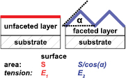
Figure 1. Schematics of the faceted and unfaceted surface geometry. The surface area in the faceted film is larger by a factor of  than that of the unfaceted layer with the facet angle α between the facet and the surface.
Download figure:
Standard image High-resolution imageA recent example for this faceting scenario is the MBE growth of the technologically important material indium oxide, In2O3. The transparent semiconducting oxide In2O3, whose stable polymorph crystallises in the cubic bixbyite structure, has been traditionally used as active material for conductometric gas sensors and in its highly Sn-doped form (called indium tin oxide, ITO) as transparent contact material. Recently, the interest in the physics and novel or improved traditional applications of In2O3 as a wide band gap semiconductor has led to the synthesis of high-quality, single crystalline In2O3 films by MBE [1]. During MBE of In2O3, indium is evaporated onto a heated crystalline substrate in the presence of a reactive oxygen flux which oxidises the indium on the substrate surface. When grown on a cubic substrate, such as the well lattice matched yttria-stabilised zirconia (YSZ), the resulting In2O3 film adopts the crystalline orientation from the substrate, growing in a cube-on-cube fashion [2]. Many authors have observed the formation of {1 1 1} surface facets for In2O3(0 0 1) grown by MBE on (0 0 1) oriented YSZ, [3–6] while the growth on (1 1 1) oriented YSZ resulted in a smooth, unfaceted In2O3(1 1 1) surface [3–6]. The preference of the (1 1 1) over the (0 0 1) surface has been explained by the polarity of the (0 0 1) surface (being either In or O-terminated) [4] and the general thermodynamic instability of polar surfaces [7]. First principle calculations of the surface tension E of the low-index In2O3 surfaces (0 0 1), (0 1 1) and (1 1 1) by Walsh and Catlow supported this view, showing that  [8]. The growth of In2O3 films on YSZ takes place in a Volmer-Weber growth mode, in which the film does not wet the substrate but nucleates into separate islands due to a higher surface free energy of the interface and film surface than that of the substrate (
 ) [9]. Continuous films can still be realised by forcing the nucleation of a high density of small islands that quickly coalesce using low growth temperatures or high oxygen fluxes [9]. Using a higher substrate temperature, in contrast, the nucleation can be inhibited to an extent that the In2O3 forms a low density of micron-sized, well separated islands [5, 9, 10]. An interesting result of the collaborative effect of low
  and inhibited nucleation is the demonstration of highly-aligned, one-dimensional In2O3(0 1 1) nanorods with {1 1 1} side facets on (0 1 1)-oriented YSZ substrates, whose large length-to-width aspect ratio has been rationalised by thermodynamic calculation based on the surface tensions [10]. A similar faceting has also been observed during the growth on r-plane sapphire substrates, which leads to the formation of (0 1 1)-oriented In2O3 by domain matching epitaxy [11]. All the above-mentioned results have been realised under the widely-used oxygen-rich growth conditions, under which more oxygen is provided than incorporated into the film and the growth rate is consequently limited by the indium flux.
Under the reciprocal, indium-rich growth conditions, in contrast, more indium is provided than incorporated into the film, the growth rate is consequently limited by the oxygen flux, and excess indium desorbs as volatile sub-oxide In2O consuming part of the provided oxygen [12]. These conditions lead to a more In-rich surface and allow the formation of smooth, unfaceted In2O3(0 0 1) surfaces on YSZ(0 0 1), which has been explained by a lowered free energy of the In-rich In2O3(0 0 1) surface [6]. First principle calculations of the surface tension dependence on the oxygen chemical potential at the surface (resulting in different surface reconstructions) by Agoston and Albe [13] are qualitatively in agreement with these experimental observations by showing a lowering of  towards lower oxygen chemical potential, which corresponds to more indium-rich growth conditions and a more indium-rich surface. Calculations from the same work also rationalise the realisation of unfaceted ITO(0 0 1) surfaces even under oxygen-rich growth conditions reported in [3, 14, 15].
This paper presents a systematic study of the In2O3 faceting on (0 0 1), (0 1 1) and (1 1 1) oriented YSZ substrates under In-rich and O-rich growth conditions, as well as for ITO grown under O-rich conditions. We demonstrate how the oxygen chemical potential during In2O3 growth can be used as an additional design parameter to control the faceting of closed films and the shape of isolated islands. In the simple thermodynamic picture that only considers surface free energies, a comparison with published theory results on surface tensions [8, 13] is made, and similarities and differences are pointed out.
2. Experiment
Closed In2O3 thin films with thicknesses in the range of 360 nm to 780 nm were grown by MBE on co-loaded (0 0 1), (0 1 1), and (1 1 1) oriented YSZ substrates. During film growth the substrate temperatures, measured by a pyrometer, were in the range of 650–700 °C. Three different growth conditions, O-rich, In-rich, and O-rich with high Sn-doping, were chosen to study their influence on facet formation and conclude on their impact on the surface stability (surface tension). The O-rich and In-rich growth conditions were identified as shown in [6] with a growth rate of  Å s−1 for In-rich and
  Å s−1 for O-rich growth conditions. Sn-doping of
  cm−3 was realised under O-rich growth conditions as described in [15]. As the results on YSZ(0 1 1) proved to be most interesting, we additionally grew a closed In2O3(0 1 1) film under approximately stoichiometric conditions. In addition, nominally 80 nm-thick, isolated In2O3(0 1 1) islands under In-rich and O-rich conditions were grown at a growth rate of
  Å s−1 utilising a higher substrate temperature to strongly inhibit the In2O3 nucleation [9]. The resulting cubic (bixbyite structure) In2O3 films or islands grew in a cube-on-cube fashion on the cubic (fluorite structure) YSZ as confirmed by x-ray diffraction measurements (XRD). Here, the out-of-plane epitaxial alignment (lattice planes parallel to the substrate surface) was determined by symmetric
  measurements, whereas the in-plane alignment and directions were determined by
  -scans (with angle
  for rotation around the surface normal) in skew-symmetric diffraction geometry measuring inclined lattice planes as described in [11]. To identify the orientation of the facets, in situ reflection high-energy electron diffraction (RHEED) was used as described in [6]. The spotty transmission diffraction pattern was used to identify the azimuth and the angle of the oblique streaks that are perpendicular to the facet surface corresponds to the angle of the facets with respect to the film surface. Scanning electron microscopy (SEM) images were taken to get an overview of the surface morphologies and its high contrast at the edges helps to distinguish the facets. In one example we analysed an atomic force microscopy (AFM) image of an In2O3(0 1 1) island to determine the facet angle and thus identify the facet type.
3. Results
Figure 2 shows the surface morphologies of the closed In2O3 films.
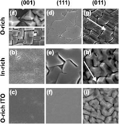
Figure 2. Plan-view SEM images showing (1 μm)2 large areas of the surface of closed In2O3 layers as a function of substrate orientation (given at the top) and growth conditions (given at the left). The white arrows denote the [01-1] direction. In (a) the morphology of two different growth runs under O-rich conditions is shown with image sizes  m
m  μm.
μm.
Download figure:
Standard image High-resolution image3.1. The (0 0 1) surface
The surface of the (0 0 1) In2O3 films tends to form {1 1 1} facets which can co-exist with additional {0 0 1} top facets under O-rich growth conditions, as shown in figure 2(a) and [5, 6, 16]. As discussed in [6] and shown in figure 2(b), In-rich growth conditions favour the growth of smooth, unfaceted (0 0 1) surfaces, and a different surface reconstruction has been reported under In-rich conditions [6]. The same holds true for the surface morphology of highly Sn-doped In2O3(0 0 1) grown under O-rich growth conditions, as shown in figure 2(c) and in agreement with [3, 14, 15].
To summarise, the In2O3(0 0 1) surface:
- forms {1 1 1} facets (exclusively or in addition to {0 0 1} top facets) under O-rich growth conditions,
- is smooth and unfaceted under In-rich growth conditions, and
- is smooth and unfaceted under O-rich growth conditions with high Sn-doping (i.e. growing ITO).
3.2. The (1 1 1) surface
In marked contrast, the (1 1 1) surface shown in figure 2(d)–(f) remains smooth and unfaceted under all growth conditions (the trenches under In-rich conditions are the result of incomplete coalescence).
In summary,
- the In2O3(1 1 1) surface is smooth and mainly unfaceted under all the investigated growth conditions.
3.3. The (0 1 1) surface
The (0 1 1) In2O3 surface shows the most diverse morphology and will be investigated in more detail.
3.3.1. The closed In2O3(0 1 1) films.
Shown in figure 2(g)–(i) form facets under all investigated growth conditions and the absence of any {0 1 1} top facet is striking. Grown under O-rich conditions, a corrugated morphology with {1 1 1} side-facets but without oblique end-facets can be seen in figure 2(g). (A qualitatively similar morphology has been observed for the growth of CaF2, having a related crystal structure to that of cubic In2O3, on Si(1 1 0) [17].) The evolution of this morphology can be assessed by the corresponding RHEED images shown in figure 3. Before growth, the vertical streaks indicate a flat YSZ(0 1 1) substrate surface (figure 3(a)), which becomes covered by In2O3(0 1 1) islands with {1 1 1} side facets, indicated by the oblique streaks, within the growth of nominally 2 nm (figure 3(b)). These islands are short enough to allow the transmission diffraction of the electron beam, which results in the spotty RHEED pattern. Judging by the fading transmission diffraction spots during further growth (see figure 3(c) and (d)), these islands coalesce to form elongated structures in the [01-1] direction that eventually cannot be penetrated by the RHEED beam any more, but maintain the {1 1 1} facets. Here, the {1 1 1} facets were identified by their orientation along the [01-1] direction and their angle of  with respect to the (0 1 1) surface.
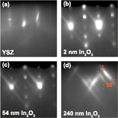
Figure 3. RHEED patterns taken along the [01-1] azimuth during the growth of the In2O3 film on YSZ(0 1 1) under oxygen-rich growth conditions at different nominal In2O3 film coverage as indicated. In (d), the dotted lines indicate the facet angle: the vertical dotted line is perpendicular to the substrate surface and the oblique dotted lines at an angle of  35° to the vertical line are drawn parallel to the oblique streaks, which are perpendicular to the inclined facet surfaces. The corresponding plan-view SEM image for (d) is shown in figure 2(g).
Download figure:
Standard image High-resolution imageHigh Sn-doping altered the faceting under O-rich conditions towards the formation of many differently indexed facets but still absent {0 1 1} top facets (see figure 2(i)).
When grown under nearly stoichiometric (figure 4) or In-rich conditions (figure 2(h)) the {1 1 1} side facets remain and oblique end-facets along the [100] directions (perpendicular to the side-facet direction) emerge. Under In-rich growth conditions these end-facets seem to cover a larger area fraction than under stoichiometric growth conditions. The facet angle with respect to the (0 1 1) surface is steeper for the end-facets than for the side facets (compare figure 4(a) and (c)), suggesting {0 1 0} type end-facets.
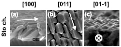
Figure 4. Bird's eye SEM images with a horizontal length scale of 1 μm (a),(c), and a (1 μm)2 plan-view SEM image (b) of a closed In2O3 film grown under near stoichiometric growth conditions on YSZ(0 1 1). The viewing direction is given at the top and the arrows denote the [01-1] direction.
Download figure:
Standard image High-resolution image3.3.2. Isolated In2O3(0 1 1) islands.
Grown on YSZ(0 1 1) were investigated to unambiguously identify the facet orientation along [100].
Their plan-view SEM and RHEED images are summarised in figure 5. For reference, 5–10 μm long and  nm-wide islands oriented along [01-1] were grown under O-rich conditions (see figure 5(a) and (b)). Their average aspect ratio (elongation along [01-1]/elongation along [100]) is as large as
  25. The long {1 1 1} side facets were identified based on the oblique streaks in the RHEED pattern taken along the [01-1] azimuth (figure 5(c)) and the plan-view SEM images indicate the absence of oblique {0 1 0} end-facets in favour of vertical (likely {01-1}) end facets. Our islands generally resemble those of [10, 16], which have also been grown under O-rich conditions but at a significantly lower growth rate, except for the absence of a small {0 1 1} top facet in our islands.

Figure 5. Plan-view SEM images of In2O3(0 1 1) islands grown on YSZ(0 1 1) under O-rich and In-rich conditions as indicated on top. Overview images (a) O-rich,  m
m  m, (d) In-rich
  m
m  m. Detailed images (b) O-rich
  m
m  m, (e) In-rich
  m
m  m. The white arrows denote the [01-1] direction. The corresponding RHEED patterns along the [01-1] and [100] azimuth as indicated within the image are shown in (c) O-rich and (f), (g) In-rich.
Download figure:
Standard image High-resolution imageFor growth under In-rich conditions, a distinctly different island morphology can be observed in figure 5(d) and (e). Instead of elongated islands with large aspect ratios we observe rectangular islands with aspect ratios between 3 and 1/3, i.e. parts of them are elongated along [01-1] and others are unambiguously elongated along [100]. The XRD scans, shown in figure 6 of this sample confirm that all islands have the same crystalline in-plane and out-of-plane orientation, i.e. they grew cube-on-cube on the single crystalline YSZ(0 1 1). The weak oblique RHEED streaks measured along the [01-1] and [100] azimuths, respectively, are at an angle of  and
and  with respect to the surface normal, indicating the presence of inclined {1 1 1} facets along the [01-1] direction and inclined {0 1 0} facets along the [010] direction. Analysis of the AFM image of an island elongated along the [100] direction, confirms this assignment, as shown in the profile lines in figure 7.
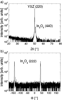
Figure 6. XRD measurement indicating singly oriented (in-plane and out-of-plane) In2O3 islands grown cube-on-cube on YSZ(0 1 1). (a) Symmetric  -ω scan indicating out-of-plane (0 1 1) oriented In2O3 on (0 1 1) YSZ. (b)
  -scan of the skew-symmetric In2O3 {1 1 1} planes. The two peaks reflect the two-fold rotational symmetry of the (0 1 1) surface indicating a single in-plane orientation without rotational domains.
Download figure:
Standard image High-resolution image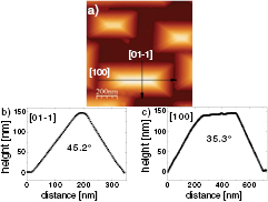
Figure 7. (a) AFM image of isolated In2O3(0 1 1) islands grown under In-rich conditions. The height profiles across one island along the [01-1] (b) and [100] (c) directions as indicated by the arrows in the AFM image are given. The extracted facet angles (half the angle between opposite facets, given in the profiles) from the [01-1] and [100] profiles clearly identify the {0 1 0} and {1 1 1} facets, respectively. For the shown islands, the {0 1 0} facets are larger than the {1 1 1} facets.
Download figure:
Standard image High-resolution image3.3.3. In summary.
The In2O3(0 1 1) surface:
- is faceted under all the investigated growth conditions without the presence of {0 1 1} top facets,
- forms exclusively inclined {1 1 1} facets under O-rich conditions,
- yields inclined {0 1 0} facets in addition to (and sometimes even with larger area fraction than) the inclined {1 1 1} facets on films or islands grown in the In-rich regime, and
- yields many different facet types (again without any {0 1 1} top facet) under O-rich conditions with high Sn-doping (i.e. growing ITO).
4. Discussion
We relate the observed faceting to the surface tension anisotropy (STA) using a simple thermodynamic model based on surface free energy only. This simple model neglects strain effects, entropy contributions to the surface tension (Gibbs free energy per unit area) at growth temperature, and kinetic barriers for facet formation. In this model the facet orientation with the lowest surface tension times area factor will mainly form on closed films (see figure 1) and the faceting of isolated islands follows the same trend but is additionally influenced by the surface tension of the substrate and the substrate-island interface as described, generally in [18] and for In2O3(0 1 1) islands on YSZ in [10]. Figure 8 shows the product of surface tension and area factor,  , for the faceting of the (abc) surface into
  facets for the lowest energy low-index In2O3 surfaces calculated by Agoston and Albe [13], and by Walsh and Catlow [8]. Here
  [with angle α between surface (abc) and facet
  as defined in figure 1 being
  for {0 0 1}(0 1 1) and {0 1 1}(0 0 1), 54.7° for {1 1 1}(0 0 1), and 35.3° for {1 1 1}(0 1 1)]. As the faceting is only determined by the relative surface tensions we have additionally scaled all the values by Walsh and Catlow by the same factor such that the (1 1 1) surface tensions of both references match. A more comprehensive, three-dimensional picture that considers the competing formation of different facets is given by the equilibrium crystal shape (ECS) that minimises the total surface free energy and can be derived from the STA using the Wulff construction [19]. Figure 9 show ECSs created by the Wulff construction using the software VESTA 3 [20] for selected STAs of figure 8. The observed changes in faceting upon changed growth conditions will be discussed in terms of the oxygen chemical potential
  at the growth surface, which is higher under oxygen-rich growth conditions than under In-rich growth conditions and decreases with increasing temperature [21].

Figure 8. Comparison of surface tension times area factor ( ) as a function of the oxygen chemical potential (
 ) for different crystallographic planes and faceting scenarios following the simple model of figure 1. (See figure 9 for the corresponding equilibrium crystal shapes.) The solid lines describe the unfaceted scenario E{abc}(abc) for the lowest energy low-index planes
  , (0 1 1) and (1 1 1) calculated by Agoston and Albe [13]. For comparison values without dependence on oxygen chemical potential calculated by Walsh and Catlow [8] 'AW' are shown as circles (the filled circle represents the actual value, the open circles represent the actual values scaled by a constant factor to match the surface tension of the (1 1 1) surface to that calculated by Agoston and Albe). The faceting of surface (abc) into facets
  , labeled '
 ', is shown by dotted lines. This faceting is thermodynamically preferred if
  . Hypothetical deviating {0 0 1} surface tensions at −2.5 eV as discussed are shown as open blue squares and marked with an '*'.
Download figure:
Standard image High-resolution image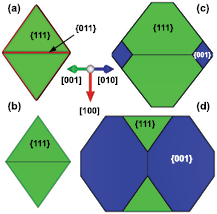
Figure 9. Equilibrium crystal shape of In2O3 determined by the Wulff construction for selected surface tension anisotropies taken from figure 8. The facet types are labelled and colour-coded (blue = {1 1 1}, green = {1 1 1} and red = {0 1 1}). The viewing direction down [011] facilitates comparison with the measured faceting of the (0 1 1) surface. Surface tension anisotropy after: Walsh and Catlow [8] (a), Agoston and Albe at  eV (b) and
  eV (c). A hypothetical scenario (d) based on surface tension anisotropies from Agoston and Albe at
  eV but with lower
  as discussed.
Download figure:
Standard image High-resolution image
4.1. The In2O3(1 1 1) surface
The In2O3(1 1 1) surface is stable, as its theoretically predicted surface tension  is lower than that of any other surface orientation for basically the entire range of
  , which explains well the formation of smooth, unfaceted (1 1 1) surfaces observed under all growth conditions.
4.2. O-rich growth of In2O3(0 0 1) and (0 1 1)
The faceting during the O-rich growth of In2O3(0 0 1) matches the predicted surface tensions by Agoston and Albe for  as well as those by Walsh and Catlow. We exemplarily chose
  eV for the discussion in the context of surface tension in figure 8 and the corresponding ECSs in figure 9(a) and (b):
The formation of {1 1 1} facets for (0 0 1) oriented films under O-rich conditions is in agreement with the  and the related ECS.
The co-existence of {0 0 1} top facets with the {1 1 1} side facets for (0 0 1) oriented films under O-rich conditions is not reflected by the ECSs but may be related to the close degeneracy  .
.
The exclusive formation of long {1 1 1} facets for (0 1 1) oriented films and islands is also in agreement with the  and the corresponding ECSs.
The complete absence of top {0 1 1} facets in our experiments is in agreement with the STA predicted by Agoston and Albe and the corresponding ECS shown in figure 9(b). The small top {0 1 1} facets reported in [10, 16], in contrast, are in complete agreement with the ECS in figure 9(a) and the surface tension anisotropy calculated by Walsh and Catlow.
4.3. In-rich growth of In2O3(0 0 1) and (0 1 1)
The faceting of In2O3(0 0 1) and (0 1 1) grown under In-rich conditions differs significantly from that observed under O-rich growth conditions and can be explained by the lowered surface tension of the {0 0 1} surface predicted by Agoston and Albe. This result demonstrates how growth conditions can control the faceting and shape of In2O3 thin films and islands. We exemplarily chose  eV for the discussion in the context of surface tension in figure 8 and the corresponding ECSs in figures 9(c) and (d):
For the (0 0 1) surface, figure 8 indicates that  eV results in
  due to a lowering of the {0 0 1} surface tension with decreasing
  , while that of {1 1 1} remains unchanged. Our experimental results on the growth of smooth, unfaceted (0 0 1) surfaces under In-rich growth conditions are in agreement with this STA scenario. This behaviour is also reflected by the emergence of {0 0 1} facets in the ECS at
  eV, which grow with further decreasing
  , as illustrated in figure 9(b)–(d). (The calculated lowering of
  at oxygen chemical potentials above −0.5 eV to the extent that smooth (0 0 1) surfaces become energetically favourable has been utilised to qualitatively explain the observation of unfaceted (0 0 1) surfaces sputtered under highly O-rich conditions [22].)
Likewise, our observed emergence of {0 1 0} facets on (0 1 1) films and islands when changing to In-rich growth conditions is in agreement with the lowering of  . The co-existence of {0 0 1} and longer {1 1 1} facets observed in our (0 1 1) closed films is well reflected by the ECS shown in figure 9(c).
The longer {0 0 1} facets than the {1 1 1} facets observed in our (0 1 1) islands elongated along [100], however, cannot be explained by the STA calculated by Agoston and Albe, as seen in figure 9(c). Instead, an even lower {0 0 1} surface tension would be required as shown by the hypothetically deviating {0 0 1} surface tensions in figure 8 (the dashed blue vertical arrow) and the corresponding ECS in figure 9(d). Similarly, the formalism proposed in [10] that relates the [0-11]-to-[100] aspect ratio of these islands to a minimisation of the surface and interface free energy, also yields the onset of elongation in the [001] upon our hypothetical lowering of the {0 0 1} surface tension.
4.4. ITO
The observed unfaceted (0 0 1) ITO surface even under O-rich growth conditions was theoretically explained by Agoston and Albe by the surface-tension lowering effect of Sn segregation leading to a Sn-rich surface. The segregation was calculated to be more likely for the (0 0 1) surface than for the (0 1 1) or (1 1 1) surfaces.
4.5. Limits, discrepancies
Despite the difficulty of defining an oxygen chemical potential for the non-equilibrium growth technique MBE, the trend of decreasing  upon changing the growth conditions from O-rich to In-rich is a reasonable assumption. In thermodynamic equilibrium at our growth temperature of 650 °C,
  would correspond to oxygen partial pressures above 10−6 mBar and at least up to 1 Bar [21]. We speculate that our O-rich growth conditions with an oxygen pressure on the order of 10−5 mBar (and the plasma excitation being unlikely to increase
  equivalent to an O2 pressure increase by a factor >108) correspond to this range of
  . It remains unclear, however, if
  eV can be realised under our In-rich growth conditions. An indium ad-layer, whose confirmation is the subject of future work, could facilitate a strong local reduction of
  at the In2O3 surface down to the stability limit of In2O3 due to the local equilibrium between In2O3 and metallic In.
The surface tensions predicted in [8, 13] were calculated in the zero-temperature limit [E(T = 0)], whereas our faceting experiments took place at  °C. To facilitate comparison with the experiment, an advanced derivation of these surface tensions should use thermodynamic data, such as the In2O3 heat of formation and In and O2 cohesive energies, at the experimentally used growth temperature. Due to the lack of surface entropy (S) data its influence on the surface tension at growth temperature [by
  ] cannot be quantified either, but may play a decisive role. For example, significant vibrational entropy contributions to the surface free energy of oxides have been suggested to influence the computed surface structures of TiO2(1 1 0) [23] or result in a strongly temperature-dependent ZnO(0 0 0 1) surface phase diagram by the stabilisation of particular ZnO(0 0 0 1) surface reconstructions out of a set of energetically almost degenerate ones [24]. Hence, the discrepancies on
  for the explanation of larger {0 0 1} than {1 1 1} facets on the (0 1 1) islands may also indicate a non-negligible entropy contribution.
To what extent the observed faceting reflects the thermodynamic equilibrium also depends on kinetic limitations for facet formation. Our well-formed facets suggest that the observed changes of faceting reflect the changing ECSs. The only exception may be the absence of {0 1 1} top facets in our O-rich experiments compared to their presence reported for similar growth experiments [10, 16] at a significantly lower growth rate and a possibly higher substrate temperature, and the co-existence of {0 0 1} and {1 1 1} facets on (0 0 1) oriented films. Another potential process that (trans)forms facets is thermally activated O and In-diffusion at high temperatures after growth. Such a diffusion is utilised, for example, for the densification of polycrystalline bulk ceramics by sintering. Post-growth annealing studies beyond the scope of this paper should elucidate this faceting pathway. The distinctly different morphology of the In-rich and O-rich (0 1 1) island samples which were both cooled down under identical conditions (at 0.25 °C s−1 under oxygen plasma and the absence of an In-flux), however, strongly suggests the dominant impact of the growth conditions on the morphology and negligible impact of the post-growth conditions in our case. Most samples were cooled down rapidly after growth, which would minimise potential post-growth diffusion.
Finally, our discussion was limited to the three lowest index surface orientations, which is justified by our observations. A refined treatment may additionally consider the rarely observed {2 1 1} facet [5], whose surface tension was also calculated by Agoston and Albe [13].
5. Summary and conclusion
We have systematically studied the surface morphology of (0 0 1), (0 1 1) and (1 1 1) oriented In2O3 and ITO films grown by plasma-assisted molecular beam epitaxy on yttria-stabilised zirconia under oxygen-rich and indium-rich growth conditions, which correspond to different oxygen chemical potentials. In a simple thermodynamic picture considering surface free energy only, the formation of the low-index ({0 0 1}, {0 1 1} and {1 1 1}) facets was compared to theoretical predictions of their surface tensions [8] and the surface-tension dependence on the oxygen chemical potential [13].
Smooth (1 1 1) surfaces can be realised under all growth conditions, whereas the (0 0 1) surface forms {1 1 1} facets under O-rich growth conditions unless heavy Sn-doping is applied (i.e. growing ITO). These experimental results confirmed the theoretical predictions of the minimum surface tension for the (1 1 1) surface, and a significantly higher surface tension for the (0 0 1) surface.
We have demonstrated how, by the changing growth conditions, the theoretically predicted dependence of the In2O3{0 0 1} surface tension on the oxygen chemical potential controls the faceting and shape of In2O3 thin films and islands, respectively: lowering the {0 0 1} surface tension by lowering the oxygen chemical potential under In-rich growth conditions prevented the formation of {1 1 1} facets on the (0 0 1) surface and allowed the complete alteration of the shape of In2O3(0 1 1) islands from elongated islands with a high length-to-width ratio and dominating side {1 1 1} facets to approximately square-shaped islands with sometimes even predominant inclined {0 1 0} side facets. These predominant inclined {0 1 0} facets under In-rich growth conditions strongly suggest a significantly lower {0 1 0} surface tension than theoretically predicted, possibly due to a non-negligible entropy contribution.
Despite its surface tension between those of (1 1 1) and (0 0 1), the (0 1 1) surface is faceted under all the investigated growth conditions, which is counter-intuitive but in agreement with constructed equilibrium crystal shapes. That is, experimentally and theoretically the (1 1 1) surface is the most stable one, whereas the least stable surface is theoretically the (0 0 1) surface but experimentally the (0 1 1) surface. Together with the complete absence of top {0 1 1} facets in our experiments, challenges in realising smooth (0 1 1) surfaces are foreseen.
Further experimental and theoretical investigations to determine the influence of kinetic limitations, entropy contributions and potential post-growth surface diffusion would further enhance our understanding of the facet formation.
Acknowledgments
We would like to thank P Vogt for assistance with the island growth, A K Bluhm for SEM imaging, H P Schoenherr for technical MBE support, and S Fernández-Garrido for critically reading this manuscript. Discussions with K Albe, H Li, O Brandt, and K H L Zhang are deeply appreciated. The authors acknowledge funding by the Deutsche Forschungsgemeinschaft under grant no. BI 1754/1-1.