
Abstract
This paper reports the successful application of ink-jet printing to the deposition of both continuous coatings and multi-filamentary structures of YBCO. Stable inks have been prepared using both the established TFA-MOD route and novel fluorine-free precursors with appropriate rheological properties for ink-jet printing. Continuous and well textured coatings with lengths exceeding 100 m and a thickness of 0.5 µm have been deposited by electromagnetic ink-jet printing from TFA precursors on LZO-buffered Ni–W substrates and samples have achieved a Jc around 1.5 MA cm−2 (self-field, 77 K). On single crystal substrates, continuous coatings and multi-filamentary structures have been deposited using piezoelectric ink-jet printing both from TFA- and water-based precursors, achieving Jc values up to 3 MA cm−2.
Export citation and abstract BibTeX RIS
1. Introduction
Ink-jet printing is the general term describing several technologies for the controllable, non-contact deposition of small droplets of a liquid on a substrate [1]. It has long been widely used for printing text and graphics, for which an ink containing a coloured dye or pigment is used, and text or images are formed by a pattern of droplets on the substrate (typically paper). However, the approach also has many key advantages for materials deposition, including the deposition of buffer, superconducting and cap layers in YBCO coated conductors.
In many respects, drop-on-demand (DOD) ink-jet printing lies between the chemical solution deposition (CSD) and vapour deposition methods conventionally used for coated conductor fabrication. It offers considerably more control, precision and flexibility than dip-coating or slot die deposition: drops of consistent volume can be dispensed with very little angular spread from a closed ink reservoir without substrate contact, reducing materials wastage and contamination of the ink supply, and allowing a uniform coating to be produced on a single side of the substrate with controllable thickness. At the same time, it is more scalable and cost-effective than vapour deposition methods, allowing deposition in ambient conditions with low capital investment.
Ink-jet printing also allows high resolution patterning (in two or three dimensions) in a single, additive deposition process. In conventional processing (solution or vapour deposition), this would usually require a separate subtractive process (e.g. lithography), resulting in additional waste and expense. The direct printing of multi-filamentary structures is a potential route towards developing low AC loss coated conductors [2–5].
For DOD graphics printing, thermal (bubble-jet) or piezoelectric printheads are usually used. In the former method, a short pulse of heat from a micro-heater is applied locally to produce a bubble of vapour: this restricts the scope of ink design, and would not be compatible with sol–gel processing. Piezoelectric printing, in which a droplet is ejected by the distortion of an ink chamber by a piezoelectric actuator, is much preferred for materials deposition. Such devices can typically produce small droplets with volumes in the range from 1 to 100 pl as a result of the small orifice diameter (typically 20–60 µm), and the ability to produce the small deflections of the ink chamber required for ink ejection with relatively high frequency drive waveforms. A third method, 'electromagnetic' or 'valvejet' ink-jet printing, uses miniature solenoid valves (micro-valves) to dispense droplets 1 nl or more in volume. These much larger drop volumes are due in part to the larger orifice diameters (typically 100 µm or above) and internal volumes, but also to their reliance on a mechanical valve to switch the flow of a continuous pressurized ink feed.
For high resolution patterning, the small drop size of a piezoelectric printhead is essential; but drops of such low mass are readily deflected in flight, so a small separation from the substrate (often ∼1 mm) must be maintained. The ink feed for these devices must also maintain a small negative pressure to retain ink at the orifice between drop ejections and, in combination with the small orifice size, this makes piezoelectric printheads susceptible to blockages by dust and air bubbles. In contrast, electromagnetic printing devices use ink delivered under positive pressure: when the valve is opened, it is this pressure which accelerates the ink from the orifice. In combination with the larger orifice size, this makes the nozzles much less susceptible to blockage, and the comparatively larger diameter and mass of the drops relaxes requirements for precise drop placement on the substrate and allows a larger distance between substrate and jetting device to be used (often ∼4 mm). Electromagnetic printing systems are used commercially for printing packaging, and provide a robust and easy-to-maintain solution when low resolution is acceptable.
In the present manuscript, ink-jet printing of coatings and tracks will be reported using both electromagnetic and piezoelectric printing systems, on both single crystals and industrially relevant metal substrates, using inks formulated based on TFA-MOD and non-fluorine chemistries.
In addition, results will be reported for YBCO films plotted on single crystalline SrTiO3(100) substrates using an ultrasonic microplotter (Sonoplot GIX Microplotter). The Sonoplot ink plotter is capable of applying picolitres of fluid continuously, creating features on a surface on a similar scale to those achievable with piezoelectric ink-jet printing. Ink is loaded by capillary forces into a hollow glass needle, which is attached to a piezoelectric element. At the resonant frequency of the loaded dispenser, the fluid is dispensed from a 10 µm diameter opening at the end of the needle. The contact maintained between the dispenser and the ink makes microplotting particularly suited to producing continuous arcs and other patterns, but at present strongly discourages its use for large-scale production. As ink needs only to be delivered to the orifice, however, rather than accelerated from it to form a single drop in flight, this technology can tolerate a very wide range of ink viscosities with less ink tuning than ink-jet printing devices.
Early work by some of the present authors and co-workers demonstrated the feasibility of ink-jet printing for the deposition of YBCO [4, 6, 7] and buffer layers [8–11] in combination with various sol–gel processing routes. The preparation of multi-filamentary YBCO coatings by the ink-jet printing of TFA-based inks has been reported using a piezoelectric micro-dispensing device [2, 12].
As discussed above, the different ink-jet and microplotting technologies have their own distinct advantages, and the most suitable choice depends on the scale, resolution and pattern of the required deposit. For this reason, an experimental comparison of the suitability of each method in YBCO deposition for identical applications has been attempted.
In the present article, the latest results are presented for the piezoelectric printing of YBCO coatings and multi-filamentary YBCO structures on single crystal substrates based on TFA and alternative non-fluorine ink chemistries. Furthermore, the transfer of electromagnetic ink-jet printing technology to an industrial scale for YBCO coated conductor deposition is demonstrated.
2. Experimental methods
2.1. Substrate cleaning
Single crystals of LaAlO3 (LAO), used as substrates for TFA-based solutions, were thermally activated by heating up to 900 °C in an O2 atmosphere for 5 h in order to remove impurities and to reconstruct the surface terminations. For the water-based YBCO solutions, single crystalline SrTiO3 (STO) substrates were cleaned with isopropanol, and were subsequently dried in air. Wetting of these two types of ink on their respective substrates became more homogeneous and repeatable. For the long length processing, a Ni–5 at.% W substrate, double coated with La2Zr2O7 (2 × 130 nm), followed by a 20 nm CeO2 layer, were used. The La2Zr2O7 and CeO2 buffer layers were deposited solely by CSD methods [13]. The complete architecture (with YBCO) is covered by a silver shunt. Before each deposition step, the substrate is cleaned following ultrasonic routines with solvents.
2.2. Ink development
TFA solutions were prepared by dissolving stable TFA salts in an alcoholic (methanol or ethanol) solvent in the presence of small amounts of polymers or polyalcohols, which allow control of the homogeneity and rheological properties of the solutions. The alcoholic precursor was prepared starting from Y(CF3COO)3⋅2H2O (98%, Sigma Aldrich), Ba(CF3COO)2 prepared by dissolving BaCO3 (99%, Panreac) in trifluoroacetic acid using a standard procedure, and Cu(CF3COO)2⋅xH2O (Alfa Aesar) salts dissolved in acetone and trifluoroacetic anhydride and heated for 24 h at 50 °C to reduce the water content. After evaporation in a rotary vacuum evaporator the resulting residue was redissolved in the appropriate quantity of the chosen solvent. The total metal concentration ranges from 0.5 to 1.5 mol l−1 verified by standard chemical redox titrations for copper and yttrium and gravimetric analysis for barium. The water content of the solutions is < 1%, controlled by Karl Fischer titration [14]. The addition of different amounts of polyethylene glycol (PEG) or 1,3-propanediol produces solutions with viscosities ranging from 1.5 to 5 mPa s [15, 16].
As an alternative, non-fluorine water-based precursor solutions were prepared by dissolving stable, cost-effective and easily available inorganic salts in an aqueous solution of coordinating ligands. As a result, solvation by water molecules is discouraged and neither extensive hydrolysis nor precipitation is likely to take place, resulting in very homogeneous materials. The aqueous precursor was prepared starting from Y2(CO3)3⋅1.9H2O (99.9%, Sigma Aldrich), Ba(OH)2⋅8H2O (98%, Janssen) and Cu(NO3)2⋅2.5H2O (98%, Alfa Aesar) salts dissolved in water and nitrilotriacetic acid (NTA, 99%, Alfa Aesar) in a 0.45:1 ratio for NTA:total metal concentration. The addition of triethanolamine (99+%, Acros Organics) increases the pH and the viscosity to the desired values of 6–8 and 4.77 mPa s (25 °C, 100 rpm, Brookfield DV-E viscometer) respectively. Attention was given to the development of an ink with neutral pH and non-aggressive components to prevent corrosion effects inside the printing system. The total metal concentration of the precursor solution was 1.1 mol l−1 (0.185 mol l−1 YBCO), as verified by ICP-OES (Spectro, Genesis). By slow evaporation of the solvent (water) at 60 °C, condensation of the complexes in the solution takes place, leading to the formation of a homogeneous gel network. A stable shelf life of several months was established. It has been reported previously that this precursor system can be used for several ceramic coatings [17–19], buffer layers [20–22] and superconductors [23, 24].
In addition to chemical stability, the precursor ink has to show the appropriate rheology leading to good drop formation from the printing nozzle and a printable flow of liquid. Viscosity is the first parameter to check, since it is crucial to obtain jetting from the nozzle [25, 26]. Low-viscosity Newtonian fluids tend to jet with break-up of the ligament into an excessive number of droplets even at the minimum stable opening time and pressure (for electromagnetic printing) or waveform amplitude and frequency (piezoelectric). Depending on the surface tension and the ink pressure control, leakage from the orifice could even occur at rest. High-viscosity fluids often require excessive energy input to jet: for electromagnetic printing systems the ink pressure becomes inconveniently high (initially approaching the rated pressure of external plastic tubing and fittings), and for piezoelectric printing the amplitude and pulse duration of the ejection waveform approach their limits. For the MacroJet electromagnetic device used here the approximate range from 2 to 8 mPa s is convenient to work with, and for the Microfab devices the viscosity should preferably not exceed 20 mPa s. The viscosity should ideally be characterized at a high shear rate, considering the high shear rate environment of a printhead.
An empirical but quantitative assessment of jettability taking into account surface tension, viscosity and orifice dimensions can be formulated based on the conventional dimensionless groupings of fluid dynamics, the Reynolds (Re), Weber (We) and Ohnesorge (Oh) numbers [6, 26]:
where σ, ρ, η and υ are the ink surface tension (J m−2), density (kg m−3), viscosity (Pa s) and velocity (m s−1) respectively and r is the diameter of the orifice of the nozzle (m). In table 1, we show the different values calculated for an optimized ink, based on the ink viscosity measured at the highest available shear rate (90 000 s−1). For the water-based ink, an Oh−1 value of 7.37 was calculated, which is within the desired range of 1–10 [6, 27]. For the TFA-based inks, the calculated values exceeded the target upper limit of 10; but it has been reported before that inks with Oh−1 numbers higher than 10 could be printed, as long as any satellites which may form merge with the main droplet before impact on the substrate [28, 29]
Table 1. Fluid properties of different YBCO inks used in this work. The Reynolds (Re), Weber (We) and inverse Ohnesorge (Oh−1) numbers are calculated for flow during ink-jet printing through the specified orifice diameter, corresponding to the Microfab devices used in the present work. Re and We are not specified in cases where the velocity during jetting is unknown.
| Type of ink | Surface tension σ (J m−2) | Density ρ (kg m−3) | Viscosity η (Pa s) | Orifice diameter (µm) | Re | We | Oh−1 |
|---|---|---|---|---|---|---|---|
| TFA based optimized for coatings | 2.15 × 10⁻² | 883 | 2.0 × 10⁻³ | 60 | — | — | 16.87 |
| TFA based optimized for patterning | 2.25 × 10⁻² | 900 | 2.4 × 10⁻³ | 60 | — | — | 14.52 |
| Water based | 6.79 × 10⁻² | 1233 | 6.8 × 10⁻³ | 30 | 15.77 | 4.58 | 7.37 |
Specific adaptation of the TFA solutions for printing has been achieved by removing additives intended for spin-coating deposition and replacing the original solvent (CH3OH) with CH3CH2OH to increase the vapour pressure and decrease the evaporation rate, thereby improving the coalescence of separate drops into a flat, continuous and homogeneous coating or structure.
Two TFA-based solutions are used in this paper, both with a 0.5 mol l−1 total metal concentration and using ethanol as solvent (see table 1). For full substrate coverage no additives were added to the solution, whereas for patterned printing 1,3-propanediol was added in order to tune the evaporation rate.
2.3. Ink-jet devices
Laboratory-scale printing of both TFA-derived and non-fluorine YBCO precursors were performed using piezoelectric micro-dispensers from Microfab Technologies (USA) mounted on X–Y positioning stages under computer control in a clean room environment. This piezoelectric device consists of a glass capillary on which a piezoelectric (PZT) tube actuator is concentrically mounted, tapering at its outlet to a small orifice. The ink feed is maintained at a slight negative pressure, retaining the ink meniscus just inside the outlet, and the application of a bipolar voltage waveform to the PZT actuator results in the ejection of a droplet. The waveform must be optimized for the ink and device: for the water-based precursor solution in a Microfab device with 30 µm orifice, the selected waveform amplitude was 20 V based on a drop visualization study. Printing was performed by moving the nozzle over the substrate at constant velocity and jetting at a constant frequency (typically 1 kHz), the ratio of these controlling the inter-droplet spacing (typically 75 µm for the water-based YBCO precursor).
For the Sonoplot with an orifice of 10 µm in diameter, the plotting speed was 500 µm s−1. A rectangular pattern of 8 × 2 mm was plotted with a thickness of 40–50 nm, which was constructed out of lines of 20 µm in width.
Long length ink-jet printing of YBCO precursor solutions for coated conductor pilot production in Deutsche Nanoschicht continuing the HTS wire activities of Zenergy Power was performed on a reel-to-reel coating line, with an online ink-jet printing device and heat treatment furnaces, for continuous production. An electromagnetic printhead (Domino Macrojet 2) consisting of seven solenoid micro-valves with approximately 100 µm jewel orifices was used with custom-made drive electronics and software to dispense the TFA-based YBCO precursor solutions over the full width of a buffered Ni–W substrate passing at constant velocity under the printhead (figure 1). The line speed (∼20 m h−1), partially constrained by the required residence time in the furnaces for heat treatment, and jetting frequency ( ∼ 3 Hz) were selected to achieve the desired inter-droplet spacing ( ∼ 2 mm). Printing was performed in a sealed cabinet with controlled humidity and solvent extraction.

Figure 1. Continuous reel-to-reel electromagnetic ink-jet printing system with subsequent online thermal treatment: schematic (left), and photograph (right) of pilot production facilities in Deutsche Nanoschicht.
Download figure:
Standard image2.4. Drop visualization
Once inks have been formulated, ensuring chemical and rheological compatibility with the chosen ink-jet printing device, drop visualization can be used to optimize the printing parameters and characterize the jetting behaviour in situ. This encompasses many time-dependent characteristics of the ink stream delivered from a single nozzle when the release of a drop is triggered. Simple quantitative parameters include the drop volume (readily adjusted for electromagnetic printing, less so for piezoelectric) and velocity, which have a direct effect on printing resolution and film thickness. In addition, the maximum length of the ink stream before a near-spherical drop is formed must be less than the printhead–substrate separation, and the production of secondary droplets forming either from break-up of the ligament (satellite drops) or secondary release from the jetting device must be minimized.
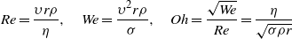
To characterize jetting behaviour and allow the optimization of ink and printing parameters, an optical drop visualization system was developed comprising a high-sensitivity camera with 1292 px × 964 px resolution at 30 frames s−1 (Allied Vision Technologies, Stingray F-125B) and a telecentric zoom lens (ML-Z07545, Moritex). Collimated, strobed LED illumination was used in a backlit configuration, as shown in figure 2. The camera shutter and LED strobe were synchronized with droplet ejection with a selectable delay time, such that each frame corresponded to the state of the ink stream a chosen time after ejection. For low frequency jetting of large droplets—i.e. > 1 nl droplets from electromagnetic printheads at < 100 Hz—this system was configured with low magnification, a strobe duration of ∼15 µs and triggered such that each image was formed from a single droplet. For piezoelectric printing, the smaller ( < 100 pl) droplets required higher magnification and consequently a much shorter strobe duration to avoid blurring. A strobe duration of 0.5 µs was used with six times higher magnification, and images were averaged over tens of successive droplets.
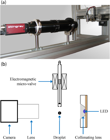
Figure 2. Apparatus for imaging ink drops during jetting, showing an ink-jet device (in this case an electromagnetic micro-valve) back-lit with a strobed LED and imaged using a camera and telecentric zoom lens: (a) photograph (edited to remove connections for clarity) and (b) schematic diagram.
Download figure:
Standard imageFor each ink and set of printing parameters, a series of images was recorded to assess the evolution of the ink stream. These could be recorded with a minimum delay time interval of 0.5 µs, but 2 µs and 50 µs intervals were typically sufficient for piezoelectric and electromagnetic printing respectively. Image analysis software was written to process and quantitatively analyse each sequence of images. In addition to 2D parameters, the centre of mass and the volume were calculated for each drop and the complete ink stream in each frame (assuming rotational symmetry for each drop), from which the velocity was also calculated.
2.5. Thermal processing
Thermal processing of the TFA-based coatings has been done in a standard way, in two steps [12]. The first is a pyrolytic decomposition at 310 °C with a dwell time of 30 min in a humid O2 atmosphere, saturated with water vapour at room temperature. The second step leads to epitaxial crystal growth at a temperature of 810 °C in a humid 200 ppm O2/N2 atmosphere for 3 h, followed by a oxygenation process at 600 °C, and a second dwell at 450 °C [30].
With respect to the water-based samples, a direct annealing process was performed [6]. The samples were heat treated at 20 °C min−1 to 780 °C for 2 h in a humid O2/N2 atmosphere, followed by an oxygenation step at 520 °C, with a dwell at 400 °C.
2.6. Measurement of superconducting properties
The critical temperature of the superconducting layers was measured by resistivity measurements as a function of temperature using a custom-made four-point test device (Keithley) and by a commercial physical property measurement system (PPMS) (Quantum Design) also using a standard four-probe method. The critical current was determined from the third harmonic of the induced signal in a pick-up coil from an AC drive signal, using a Theva Cryoscan setup in liquid nitrogen. For this inductive measurement, a constant-voltage criterion of 50 µV was selected. The uniformity of superconducting coatings and patterns has also been assessed using a scanning Hall probe, for samples cooled in liquid nitrogen and magnetized to full penetration.
Magnetic measurements were made in a DC superconducting quantum interference device (SQUID) magnetometer (Quantum Design MPMS-XL7T). Cooling the sample in a zero-field-cooling (ZFC) process down to 5 K, an M(H) loop was taken with a maximum field of 30 kOe. Then, an M(T) curve was recorded from 5 to 95 K. In order to measure Tc, the sample was cooled down to 10 K with no applied field, and a low-field M(T) curve was obtained up to 100 K.
Critical current measurements were also performed as a function of the orientation of an applied magnetic field. These direct in-field transport current measurements complement the self-field Jc results obtained from the inductive Cryoscan method. In addition, the orientation dependence allows any anisotropic pinning contributions or vicinality of the substrate to be detected [31].
The measurement system consists of a two-axis goniometer probe mounted vertically between the poles of a fixed horizontal electromagnet [31]. The sample can be precisely oriented around two perpendicular axes using computer-controlled stepper motors: the whole probe can rotate about its long vertical axis ('rotation'), and a moving sample platform can rotate about a perpendicular axis through the mid-point of the sample platform ('tilt'). Current is transferred to the tilting platform by sliding contacts.
Tape samples ∼36 mm long were mounted on the tilting platform, with the current parallel to the length of the tape and a typical voltage contact separation of 6 mm. The current contacts between the sample and the tilting platform were soldered using indium, and voltage taps were attached with silver paint. The critical current was measured in liquid nitrogen as a function of two-axis orientation, extracting Ic and the n value from automated power-law fits to the measured voltage–current characteristics using a 1 µV cm−1 criterion.
2.7. Morphological and structural characterization
The composition, crystallinity and texture of the processed films was verified using x-ray diffraction, both in the Bragg–Brentano configuration for phase identification and configured for texture analysis (Thermo Scientific ARL X'TRA and Bruker D8; Cu Kα). The sample morphology was characterized using optical microscopy (Leitz, Laborlux 12 POL S, and Olympus, U-CBE) and SEM (FEI Nova 600 Nanolab dual-beam FIB and FEI Quanta 200 FEG). A cross section of the layers was made using a FIB module coupled with SEM to verify the thickness of the layers. The topology of multi-filamentary patterns was visualized using optical and AFM profilometry (Veeco NT9080 and Tencor KLA P16).
3. Results and discussion
3.1. Coatings from TFA-based precursors
The TFA-based precursor solution described above was found to be fully jettable in the 60 µm Microfab piezoelectric micro-dispenser, producing drops with a volume of ∼30 pl, and continuous surface coatings were achieved on a LAO single crystal substrate (figure 3). The homogeneity of the deposition is not affected by the drop pitch in the range from 20–35 mm. The layers obtained are homogeneous and their thickness can be easily controlled by adjusting the density of drops over the substrate surface in terms of the drop pitch. The layers are grown epitaxially (figure 4) in a single deposition up to 600 nm thick. The in-plane and out-of-plane structure of both layers is very good, resulting in FWHM for φ and ω scans for both layers of respectively 1.5° and 0.6° (300 nm thick) and 1.6° and 0.7° (600 nm thick). The 600 nm thick layer exhibits Jc values over 1.2 MA cm−2 at 77 K. Critical currents as high as 3 MA cm−2 have been achieved for layers up to 300 nm in thickness.

Figure 3. Full YBCO coatings produced from TFA-based precursors on LAO substrates, visualized by optical microscopy after pyrolysis (left) and SEM after complete processing (right). The superconducting coating thickness of the upper and lower samples after processing are 300 and 600 nm respectively, corresponding to a Jc of 3 and 1.2 MA cm−2.
Download figure:
Standard image
Figure 4. θ/2θ XRD pattern showing epitaxial growth of a 600 nm thick YBCO coating prepared from a TFA-based precursor on an LAO substrate.
Download figure:
Standard imageYBCO tracks (multi-filamentary patterns) have also been tested. In order to diminish slightly its wetting ability in order to avoid excessive spreading of the solution on the surface of the LAO substrate, 1,3-propanediol was added to the ethanol-based TFA solution. Parallel, continuous and uniform tracks were deposited over single crystal LAO substrates. The quality of these tracks is displayed in figure 5. Optical micrographs after pyrolysis (figures 5 (a) and (b)) demonstrate the curvature of the track edges with a homogeneous profile. SEM micrographs in figures 5(c) and (d) show the homogeneous and uniform structure typical for fully processed YBCO coatings.
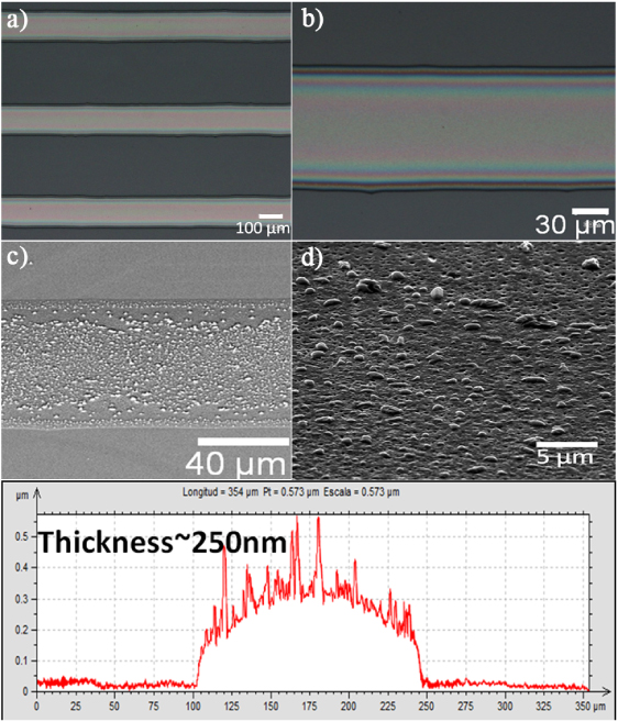
Figure 5. Optical ((a), (b)) and SEM ((c), (d)) micrographs of the ink-jet printed TFA-based YBCO tracks, after pyrolysis and complete processing respectively, showing remarkable homogeneity of the tracks. Profilometry measurement of the tracks (bottom) shows the expected elliptic-like shape according to the surface forces.
Download figure:
Standard imageAFM profilometry allows determination of the shape of the cross-section of a track. The result in figure 5, shows that the transverse cross-section of the track corresponds to equilibrium of the surface forces, giving an elliptic-like profile. The thickness in the tested region was 250 nm.
The deposition of tracks and arbitrary patterns has also been demonstrated. In figure 6, an example of an arbitrary YBCO pattern is shown. The printout of the logo has been performed over a 10 × 10 mm2 single crystal of LAO. A high quality of resolution is achieved, as a result of the high repeatability in placement and volume of the drop emitted by the dispenser and the high resolution of the positioning system. In this case, the accuracy of the positioning system is better than two microns.
Samples have been tested for homogeneity by Hall mapping the remanent field after magnetizing the sample up to full penetration. The distribution of the magnetic flux is in good agreement with that expected for homogeneous deposition and the interpretation of this kind of map can be found elsewhere (figure 6) [12, 32].
Figure 6. SEM micrograph (left) with a detail of an YBCO pattern, printed over a 10 mm × 10 mm LAO substrate, starting from a TFA-based YBCO ink. Hall mapping (right) of the remanent magnetic field trapped by the YBCO coating shows good homogeneity of the deposition.
Download figure:
Standard image3.2. Coatings from water-based precursors
As an alternative to TFA precursors, ink-jet printing with fluorine-free inks was tested starting from water-based precursor designs. Specific attention was given to the stability of metal ions in hydrolytic media and to the wetting behaviour of the water-based ink on the selected substrates. In order to predict the stability of the ink, the complexation behaviour of the complexing agents added as a function of pH with the different metal ions can be calculated using specific software (Hyss2006). This software can calculate speciation plots based on stability constants taken from literature or experimentally obtained. There is also the possibility to take precipitation into account.
The decision to select TEA and NTA as good candidates for increasing the stability of the metal ions in solution was made based on the ability to use the free electron pair of N or the deprotonated carboxylic groups for strong complexation with the metal ions [33–35]. An ink with a long shelf life can be obtained when the concentration of free metal ions or the presence of dissolved hydroxides, which can result in precipitates which destroy the homogeneous distribution of the metal ions in the ink, is almost negligible.
In figure 7, a compilation of the most important species present in solutions with the concentrations and ratios described in the experimental section is given. Detailed information on this subject can be found in [6, 36]. Two boundaries can be defined for the pH values leading to stable precursor designs: a minimum pH of 6 and a maximum pH of 10. The former restriction is due to the presence of free Y3+ , and the latter is due to the formation of a precipitate of Y(OH)3. Special care needs to be taken with the presence of free barium ions. A relatively large fraction of these free ions stays in solution until a pH of 10 and, from then on, complexation with NTA becomes possible because yttrium releases NTA with the formation of the hydroxide. Because it is experimentally seen that stable precursor inks within a pH region from 6 to 8 can be obtained, these free Ba2+ ions are possibly prevented from precipitation due to the presence of other intermolecular forces such as ion–dipole interactions and H bridges.

Figure 7. Theoretical speciation for a solution containing 0.4737 mol l−1 Cu(NO3)2, 0.1579 mol l−1 Y2(CO3)3, 0.3158 mol l−1 Ba(OH)2, 0.4263 mol l−1 NTA and 1.5863 mol l−1 TEA, showing the relative concentration of each metal species as a function of pH. The dotted line marks the possible speciations of Y3+ and the striped lines refer to the speciations of Ba2+.
Download figure:
Standard imageThe stable water-based inks were afterwards optimized towards good rheology for printing with the properties given in table 1, leading to good jetting behaviour, i.e. without the formation of satellite droplets and with a stable trajectory of the drops in flight, and good wetting behaviour on single crystal STO substrates.
For the specific example in figure 8, showing jetting of a water-based YBCO precursor as a function of delay time (the time elapsed after triggering of the actuator system) from a 30 µm Microfab piezoelectric micro-dispenser, one can see that initially the ink forms a column which transforms into the actual droplet and an elongated tail. For the conditions shown here, break-up of this tail leads to the formation of a satellite drop. The presence of these satellite droplets should be avoided at impact with the substrate, as the key goal is to leave a single isolated droplet to optimize precision, resolution and accuracy during printing. Therefore, the jetting parameters, ink formulation and the distance between the nozzle and the substrate should be chosen in such a way that multiple droplets (if present) can merge before impact. The nozzle–substrate separation must generally be minimized for accuracy, because drag from air currents in the printing chamber makes the droplets deviate from their vertical trajectory. In our case, the optimal distance between printhead and substrate was determined to be between 0.6 and 2 mm, and in the illustrated example a single drop was formed within 0.5 mm of the orifice.

Figure 8. (a) The vertical displacement of the centre of mass (CoM), number of drops and total ink volume of the water-based YBCO ink during jetting as a function of the strobe delay time (the time elapsed after triggering the piezoelectric actuator), obtained by quantitative image analysis of drop visualization images. The volume fluctuations do not represent changes in volume of the ejected ink drops, but correspond to momentary excursions of the unejected ink column in the dispenser as it undergoes damped oscillations, as discussed in the text, and (b) a selection of drop visualization images at the specified delay times after the ejection trigger, confirming coalescence of the ink stream into a single drop within 0.5 mm of the orifice.
Download figure:
Standard imageThe estimated volume and velocity of droplets of the water-based precursor ejected from this Microfab device can vary within the range of a few picolitres to 80 pl and 2.3–3.5 m s−1 respectively within the printing parameters tested. For the experiment displayed in figure 8, the volume is around 70 pl with a droplet velocity of 2.9 m s−1 after merging at 250 µs. At 105 µs, the estimated volumes for the main droplet and the satellite are close to 60 pl and 10 pl respectively.
The chart showing the vertical position of the centre of mass, total ink volume and droplet count confirms the quantitative details of the time-dependent jetting behaviour of the Microfab device (figure 8(a)). The ejected ink moves at constant velocity (the line showing the displacement of the centre of mass is of constant gradient) and remains of constant volume despite the separation of the ink stream into two separate drops near a delay time of 105 µs and their subsequent recombination (also seen in figure 8(b)).
Additional features superimposed on that trend correspond to the behaviour of the unejected ink column in the dispenser. The small decrease in volume from the initial maximum shows the recovery of the initial ink excursion, after which a periodic sequence of simultaneous troughs in centre of mass position and peaks in volume, with an apparent increase in the number of 'drops', corresponds to oscillations of the ink column during which some ink momentarily extends below the orifice before relaxing back inside the dispenser. These oscillations are a result of the acoustic wave established by the bipolar waveform applied to the piezoelectric element, and are damped over time, with the meniscus eventually recovering the equilibrium position defined by the small negative pressure applied to the ink supply. Where the number of drops changes without a significant change in volume or centre of mass position in figure 8(a), this corresponds to the appearance and coalescence of satellite drops as shown in figure 8(b).
In figure 9, optical and profilometry images are presented of wet droplets, dried at 100 °C. The diameters and heights of the droplets in the two left images vary in the ranges 145–160 µm and 40–160 nm respectively and, for the pattern, between 120 and 140 µm and between 170 and 20 nm respectively. Due to the small volume of material in one droplet or a single printed line, with rapid solvent evaporation from the edges, a clear 'coffee-ring' effect can be observed in the profilometry measurements.
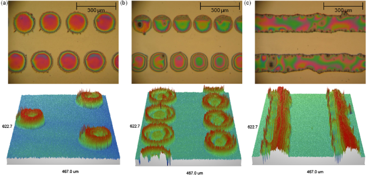
Figure 9. Optical micrographs and interference profilometry profiles for droplets of the YBCO water-based ink, printed with longitudinal spacings of (a) 0.2 mm, (b) 0.15 mm and (c) 0.1 mm, demonstrating that both continuous coating and patterning are possible.
Download figure:
Standard imageWhen bringing the droplets closer together in the axial direction, it becomes equally possible to change from printing a pattern to achieving complete coverage of the substrate. The thickness after complete heat treatment of the YBCO thin films varies between 310 and 400 nm. Microstructural investigation of the top layer by SEM (figure 10) shows a crack-free and dense surface. However, secondary phases enriched by Ba and Cu are visible. The morphology will be further improved by an optimization of the heat treatment.
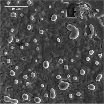
Figure 10. Topographical SEM micrograph of a fully coated substrate prepared from a water-based YBCO precursor after complete processing.
Download figure:
Standard imageXRD patterns reveal the formation of crystalline films of pure YBCO (figure 11(a)). The in-plane and out-of-plane misorientation of the YBCO film was further characterized by a φ scan (figure 11(b)) and ω scan (figure 11(a), inset). An average full width at half maximum (FWHM) value of 1.87° for the (103) φ scan and an FWHM of 0.68° for the (005) ω scan proves that highly textured YBCO was obtained. The critical current density of the YBCO film at 77 K in self-field was measured inductively to be 0.67 MA cm−2 for an YBCO layer thickness of 350 nm using the third harmonic of the induced signal [6].
Using an ultrasonic microplotter (Sonoplot), YBCO layers were continuously plotted, starting from the same water-based ink, on STO substrates with a subsequent annealing at a crystallization temperature of 790 °C. The superconducting transition temperature of a representative YBCO film was measured by a standard four-probe method. The result evidences a high critical temperature Tc(50) ≥ 92 K and a sharp transition into the superconducting state.
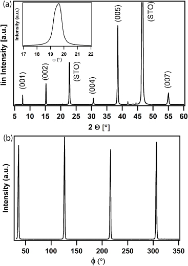
Figure 11. (a) θ–2θ scan and ω scan of the (005) plane (inset) and (b) φ scan obtained for the (103) plane of the water-based YBCO ink after complete conversion with an average FWHM for the last two of 0.68° and 1.87° respectively.
Download figure:
Standard image3.3. Long length ink-jet printed coated conductors
TFA precursors were printed using an electromagnetic ink-jet printhead to deposit YBCO on buffered Ni–W substrates using a continuous reel-to-reel system. Dense coatings with an average thickness around 500 nm were successfully produced on top of 250 nm thick LZO buffer layers also prepared by CSD methods (figure 12). Continuous samples in excess of 100 m long have now been produced.

Figure 12. SEM cross-section view of HTS tape: 450 nm HTS layer thickness, 250 nm buffer layer thickness.
Download figure:
Standard imageCritical current densities in the superconducting layer well above 2.0 MA cm−2 on 6 mm wide tapes illustrate the epitaxial growth of ceramic layers on the metal substrate. A low standard deviation in these values is shown even over long lengths of the tape, and critical currents around 100 A cm−1 width and n-values exceeding 30, in self-field at 77 K, are obtained for lengths up to 10 m. The values for wire lengths exceeding 100 m show good homogeneity in the range of 1.5 MA cm−2 and no severe defects interrupting the superconductivity over the total length (figure 13).
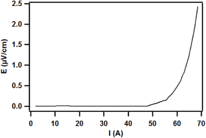
Figure 13. Critical current measurement of ink-jet printed YBCO on buffered Ni–W tape with a 6 mm width and 1.5 m long (sample cut from a 12 m long coated conductor tape).
Download figure:
Standard imageThe progress in critical current performance and continuous long length production at Deutsche Nanoschicht, continuing the HTS wire activities of Zenergy Power, in recent years is summarized in figure 14. This is described by the product of the longest sample length and the corresponding critical current (in A m), reflecting the ability to process long lengths with high performance. The value achieved this year, of more than 9000 A m, is the best ever reported for an all-CSD coated conductor with an ink-jet printed HTS layer.
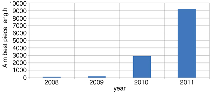
Figure 14. Length × critical current of best piece lengths produced using ink-jet printing by Deutsche Nanoschicht.
Download figure:
Standard imageA short sample of 10 mm wide tape was mounted for measurement on the two-axis critical current goniometer stage, and the transport critical current was measured in liquid nitrogen over a large angular range of both rotation (−120°–120°) and tilt (−100°–100°). To facilitate comparisons of the angular dependence of Ic between different samples and for tests at different magnetic fields, these critical currents were normalized against the value at 0° tilt and 90° rotation: this is the orientation with current perpendicular to magnetic field (as required for most applications) and the magnetic field in the plane of the substrate, and would correspond to the ab peak for a textured YBCO film on a non-vicinal substrate. A three-dimensional representation of these results for an applied field of 0.592 T is shown in figure 15.
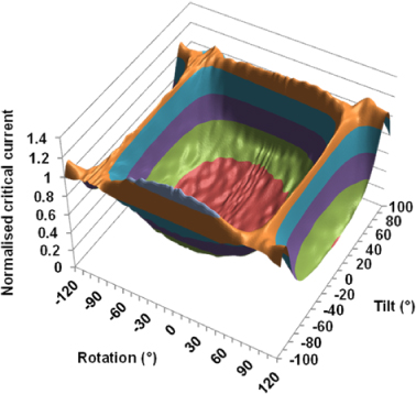
Figure 15. The dependence of the normalized critical current on the two-axis orientation of an ink-jet printed coated conductor sample relative to the external field (0.592 T, liquid nitrogen). Each band corresponds to an increment of 0.2 with a maximum of 1.17.
Download figure:
Standard imageThe scan was repeated with a lower applied field of 0.4 T. The critical current was on average 27% higher than at 0.592 T, but the shape and symmetry of the orientation dependence was unchanged (figure 16). Measurements on a similar sample with a slightly lower Jc of 1.15 MA cm−2 (CryoScan, self-field), not presented here, followed the same trend.
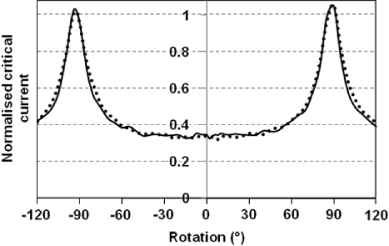
Figure 16. The dependence of the normalized critical current on the rotation angle between the external field and the substrate normal, measured on an ink-jet printed coated conductor sample at 0.592 T (solid line) and 0.400 T (dotted line) (liquid nitrogen).
Download figure:
Standard imageThe symmetry of this behaviour in both rotation and tilt, with peaks at ±90° in rotation, confirms that the ab plane of the YBCO film is well aligned with the substrate plane. The anisotropy of Ic in rotation is typical of an YBCO film without aligned defects or artificial pinning centres, as would be expected for chemical solution deposition of an undoped YBCO composition as employed here. To obtain these results, 1281 transitions were measured at each tested magnetic field without stability problems, and an average n value of 19 was observed, comparable to commercial MOD-RABiTS samples measured at a similar temperature and field [37].
Taken together with the CryoScan measurements, these results confirm that the performance of these samples is in the range expected for solution deposited undoped YBCO coated conductors without engineered pinning, and that small-sample results for ink-jet printing can be scaled to long lengths without significant degradation. This performance is already sufficient for some low-field applications of YBCO coated conductors, and gives a promising indication that higher-performance samples can also be produced if the successful work on introducing engineered pinning to chemical solution deposited YBCO films reported here and elsewhere by the present authors is transferred to long length ink-jet printing.
4. Conclusions
Inks have been prepared using both the established TFA-MOD route and novel fluorine-free formulations with appropriate rheological properties for ink-jet printing using both piezoelectric and electromagnetic technologies.
Continuous and well textured coatings with lengths exceeding 100 m and a thickness of 500 nm have been prepared from TFA precursors on LZO-buffered Ni–W substrates using electromagnetic ink-jet printing, and samples have achieved a Jc around 1.5 MA cm−2 (self-field, 77 K). The buffer layers were also prepared by a chemical solution deposition (CSD) route, and this all-CSD route shows good potential for low cost long length industrial production.
On single crystal substrates, both TFA- and water-based precursors have been printed, producing well textured coatings with Jc values up to 3 MA cm−2. Multi-filamentary structures and even arbitrary patterns have been successfully prepared, demonstrating the potential for ink-jet printing to directly deposit the structures desired for low AC loss coated conductors without masking, etching or slitting processes.
Further work will focus on applying the methods developed for multi-filamentary printing and nanoparticle additions on single crystal substrates to buffered Ni–W substrates, and implementing these methods for long length reel-to-reel deposition.
Acknowledgments
Work was partially carried out under EFECTS, a project funded by the European Union, FP7-NMP-2007-SMALL-1 grant no. 205854 and by the contribution of Spanish national projects 'Nanoselect' and MAT2008-01022.