

Abstract
Chest tomosynthesis is a low-dose, quasi-3D imaging modality that has been demonstrated to improve the detection sensitivity for small lung nodules, compared to 2D chest radiography. The purpose of this study is to investigate the feasibility and system requirements of stationary chest tomosynthesis (s-DCT) using a spatially distributed carbon nanotube (CNT) x-ray source array, where the projection images are collected by electronically activating individual x-ray focal spots in the source array without mechanical motion of the x-ray source, detector, or the patient. A bench-top system was constructed using an existing CNT field emission source array and a flat panel detector. The tube output, beam quality, focal spot size, system in-plane and in-depth resolution were characterized. Tomosynthesis slices of an anthropomorphic chest phantom were reconstructed for image quality assessment. All 75 CNT sources in the source array were shown to operate reliably at 80 kVp and 5 mA tube current. Source-to-source consistency in the tube current and focal spot size was observed. The incident air kerma reading per mAs was measured as 74.47 uGy mAs−1 at 100 cm. The first half value layer of the beam was 3 mm aluminum. An average focal spot size of 2.5 × 0.5 mm was measured. The system MTF was measured to be 1.7 cycles mm−1 along the scanning direction, and 3.4 cycles mm−1 perpendicular to the scanning direction. As the angular coverage of 11.6°–34°, the full width at half maximum of the artifact spread function improved greatly from 9.5 to 5.2 mm. The reconstructed tomosynthesis slices clearly show airways and pulmonary vascular structures in the anthropomorphic lung phantom. The results show the CNT source array is capable of generating sufficient dose for chest tomosynthesis imaging. The results obtained so far suggest an s-DCT using a distributed CNT x-ray source array is feasible.
Export citation and abstract BibTeX RIS
1. Introduction
Digital tomosynthesis is an imaging modality that produces 3D sectional information by using x-ray projection images acquired over a limited scanning angle (Dobbins and McAdams 2009, Tingberg 2010). The projection images are reconstructed into a sequence of tomosynthesis slices, each focused at a different distance from the detector. Tomosynthesis reduces tissue overlap, provides increased contrast of anatomic structures, and gives more precise depth localization compared to conventional chest x-ray radiography (CXR). This technology is currently in clinical use for breast, chest, sinonasal, abdominal, and musculoskeletal imaging (Duryea et al 2003, Gomi and Hirano 2008, Dobbins and McAdams 2009, Mermuys et al 2010, Machida et al 2012). Clinical studies have demonstrated that digital chest tomosynthesis (DCT) improves the ability to detect small lung nodules in comparison to CXR, and at a much lower dose than chest computed tomography (CT) (Dobbins et al 2008, Vikgren et al 2008, Dobbins and McAdams 2009, Sabol 2009, Båth et al 2010, Yamada et al 2011). Other than lung nodules, DCT also shows improved diagnostic ability in detecting other lung pathology, such as bronchiolitis, pulmonary consolidation, pulmonary emphysema, and cystic fibrosis when compared to CXR (Kim et al 2010, Vult von Steyern et al 2012, Yamada et al 2013).
DCT systems in use today uses a single-beam x-ray source that moves to collect a set of low dose projection images acquired from multiple angles. Several prototype and commercial DCT systems have been developed (Dobbins et al 2008, Vikgren et al 2008, Dobbins and McAdams 2009, Rivetti et al 2011, Yamada et al 2011, Terzi et al 2013, Yamada et al 2013). These systems were mostly based on clinical in-room digital radiography system. The prototype scanner developed at Duke University was reported to perform a tomosynthesis scan of 71 projections over a 20° angular sweep within 11 s (Dobbins et al 2008, Dobbins and McAdams 2009). The GE VolumeRAD (GE Healthcare, Chalfont St Giles, England) system has been used clinically for several years (Vikgren et al 2008, Båth et al 2010, Quaia et al 2012, Terzi et al 2013). In this system, the x-ray tube is mounted on an overhead tube suspension system that moves vertically with a variable source-to-detector distance of 180–187 cm. A typical tomosynthesis scan takes 10 s and includes 61 low dose projections over 30° (Vikgren et al 2008, Quaia et al 2012). The tomosynthesis radiographic technique varies from patient to patient. The mAs per projection was generally determined using a scout view (Sabol 2009, Båth et al 2010, Terzi et al 2013). A standard chest posterior-anterior (PA) radiography was taken as scout view, the mAs from scout view was multiplied by a ratio (usually 10), then divided by the total number of projection views to derive the mAs per projection (Sabol 2009). The relatively long scanning time, approximately 10 s, leads to image blur due to patient motion (Yamada et al 2011). In the Shimadzu SONIALVISION (Shimadzu, Japan) DCT, both the x-ray tube and the detector move linearly in opposing directions. A set of 74 projections are acquired over a 40° angle in 5 s (Yamada et al 2011). However, in systems with a moving x-ray source, there is a tradeoff between the scanning time and tube moving speed. In general, the shorter the scanning time, the faster the tube needs to be moved. This can be mechanically challenging, and may lead to blurring due to x-ray source focal spot motion during the detector integration time.
We have recently developed a carbon nanotube (CNT) based distributed field emission x-ray source array technology (Zhang et al 2005, Zhou and Calderon‐Colon 2010). The technology utilizes an array of individually controllable CNT emitters as the 'cold cathodes' to generate electrons, which are accelerated toward and bombard the anode to generate x-ray radiation. By electronically switching the individual CNT cathodes on and off, a scanning x-ray beam is generated by different focal spots on the x-ray anode without any mechanical motion (Zhang et al 2005, Zhou and Calderon‐Colon 2010). The CNT x-ray source array is particularly attractive for tomographic imaging because the projection views are acquired from different angles without mechanical motion. This technology enables stationary tomography with fast scanning speeds and high image resolution by eliminating imaging blur due to source and patient motions. It also opens up the feasibility of designing tomography scanners with novel geometries, as stationary imaging with multiple sources removes the issues associated with managing the momentum of heavy x-ray sources moving in multidimensional paths. The application of the distributed CNT x-ray source array for stationary tomography has recently been demonstrated for digital breast tomosynthesis,(Qian et al 2009 2012) tomosynthesis image guidance for radiation therapy, (Maltz et al 2009) a novel tetrahedron CT concept, (Xu et al 2011) and stationary CT for homeland security (Gonzales et al 2013). The purpose of this research is to investigate the feasibility of stationary digital chest tomosynthesis (s-DCT) using a CNT x-ray source array, and the system requirements for the source array for s-DCT.
2. Methods and materials
A bench-top system was set up using a linear x-ray source array containing 75 focal spots and a flat panel detector, as shown in figure 1. The linear source was characterized. The x-ray output and beam quality were measured. Focal spot sizes of multiple spots were measured using pinhole. Projection images of a cross wire phantom were acquired and reconstructed to measure the system modulation transfer function (MTF) and the artifact spread function (ASF) as quantitative measurements of the system in-plane resolution and in-depth resolution, respectively.
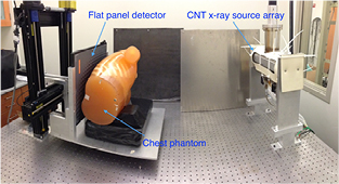
Figure 1. Bench-top stationary chest tomosynthesis system. The linear CNT x-ray source array consists of 75 x-ray generating focal spots. The detector and phantom, mounted on the same stage, can be translated to simulate different imaging geometries.
Download figure:
Standard image High-resolution image2.1. Distributed CNT x-ray source array characterization
The CNT x-ray source array (Model 2008-08-L75-002, XinRay System Inc., Research Triangle Park, NC) contains 75 linearly distributed x-ray focal spots with a 4 mm pitch, and an end-to-end spacing of 296 mm. Each x-ray source consists of a CNT cathode, gate and focusing electrodes, and an elongated tungsten anode shared with other sources. The cathode is grounded, while the gate electrode is applied a positive voltage to extract electrons from the cathode via the field emission effect. The field emission current is controlled by the electric field applied between the gate electrode and cathode. The maximum output current, as in conventional x-ray tubes, is limited by the thermal management of the anode, and is influenced by interplay of many factors including the focal spot size, the anode voltage, the pulse width, and the duty cycle. The x-ray tube current, defined as the current that reaches the anode, is less than the cathode emission current due to leakage primarily to the gate electrode. The electron transmission rate, defined as the ratio of tube current to the emitted cathode current, as well as the gate voltage required for each cathode corresponding to a certain current, are used to characterize the CNT x-ray source. The tungsten anode has a 12° tilting angle relative to the x-ray window. A 2 mm aluminum window serves both as the vacuum barrier and as the inherent filter.
The CNT x-ray sources' stability was measured. The source stability is quantified as the cathode-gate voltage change for a fixed anode current over time. A source stability test was performed over a four-month period, during which the x-ray source was used multiple times a day. The tube current, cathode-gate voltage, tube output in mAs, pulse width, and the date were recorded and logged into a database.
The focal spot size of each individual x-ray sources in the array was measured using the pin-hole method described by the European standard EN12543-2. (EN 12543-2 1999) The tungsten pinhole used in the measurement was 400 μm in diameter and 2 mm in thickness. The pinhole images were acquired using a CsI based flat panel detector (Carestream DRX-1C). The pinhole was placed between the source array and the detector. The ratio between detector-to-pinhole distance and source-to-pinhole distance was roughly 3:1, as recommended in the standard, to gain enough magnification. The exact magnification factor was determined later by analyzing the projection images. The pinhole was carefully aligned to the focal spot, whose location was determined using a system geometry calibration procedure. The images were corrected by the flat field air image to get uniform background, and then the intensity in the pinhole was measured, normalized, and fitted into a 2D-Gaussian distribution. The full-width-at-half maximum (FWHM) values in both parallel (x) and perpendicular (y) directions to the scanning direction were measured and used as the focal spot size.
2.2. System description
The bench-top chest tomosynthesis system, as shown in figure 1, consists of the CNT linear x-ray source array, a CsI based flat panel detector (Model DRX-1C) manufactured by Carestream Health Inc. (Rochester, NY) mounted on a translation stage, a phantom stage, and an electronic control unit. The detector, which was originally designed for radiographic imaging purpose, has a field of view of 35 × 43 cm and a 139 μm pixel size. The integration time can be adjusted from 260 to 1100 ms. The detector requires a frame by frame external trigger to acquire a sequence of images. Since the x-ray source array used in this study has a relatively short length, the detector and the phantom are mounted on a translation stage to achieve a wider range of imaging geometries. A LabVIEW program was made to automate the x-ray tube operation and image acquisition. As illustrated in the timing diagram in figure 2, the computer generates a sequence of trigger signals to trigger the detector read-out, followed by the detector ready-to-exposure signal which is synced to the x-ray source switching system. The x-ray source switching system is programed to switch and fire each x-ray source based on the sequence set by the operator. The x-ray sources can be fired in any sequence, either one-by-one from one end to the other, or in a pre-defined pattern.
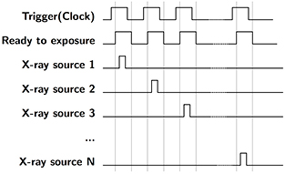
Figure 2. Timing diagram for s-DCT imaging. Computer generates a trigger signal to externally trigger the detector. The detector ready-to-exposure signal is synced to the x-ray source switching system, where each pulse will be used to trigger a single CNT x-ray source in the source array. The CNT sources are fired in a sequence preset by the operator.
Download figure:
Standard image High-resolution imageThe system geometry is shown in figure 3. The source-to-detector distance is 110 cm, with the source array aligned to the centerline of the detector. The 75 focal spots with 4 mm pitch, in the present x-ray source array, cover a 15.7° angular span relative to the detector center. Translation of the detector and the phantom together, relative to the source array, allows extended acquisition geometries with variable source-to-detector distances, angular coverage, and number of projection views. Due to limitations of the optical table size, the maximum effective source array length that can be emulated is 672 mm. However, the resulting 34° angular coverage relative to the detector center is comparable to current commercial systems. This effective source array has a source-to-source pitch of 4 mm and can generate up to 169 projection views. By choosing different combinations of sources, one can simulate various imaging configurations with different numbers of projections, angular span, and source-to-source pitch. For most images acquired in this study, we used every other source in this effective source array. This produced up to 85 projections with 0.4° angular steps between projections, which is comparable to commercial DCT systems.
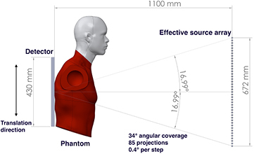
Figure 3. An illustration of the imaging geometry in the bench top stationary chest tomosynthesis system. The source-to-detector distance is 110 cm. By moving the detector and phantom together, parallel to the source array, we are able to emulate different imaging geometries. In the current bench-top proof-of-concept setup, the effective x-ray source array is able to cover up to a 34° angular span relative to the detector center with up to 85 projections.
Download figure:
Standard image High-resolution imageTo reconstruct the tomosynthesis dataset from the projection views, the geometric relationship between the x-ray sources and the detector is required. The relative locations of each of the focal spots are determined by a geometry calibration procedure that utilizes the projection images of a phantom with metal beads positioned at different source-to-object distances to calculate the coordinates of each source relative to the center of the detector.
2.3. X-ray output and beam quality
The x-ray output and beam quality of the x-ray source array were measured. The radiation dose was measured using a solid-state dosimeter (Unfors Mult-O-Meter 470L) manufactured by Unfors Instruments AB and calibrated 3 months before measurements. (Billdal, Sweden). The dosimeter effective energy range is from 50 to 150 kVp. Due to the x-ray source array was not designed for medical applications originally, a 0.8 mm additional aluminum filter was added to comply with the beam quality requirement for medical imaging. Combined with the 2 mm aluminum inherent filtration, the total filtration of the source array is 2.8 mm aluminum.
The dosimeter probe was aligned to the x-ray tube and was placed 100 cm away from the focal spot without the presence of phantom or patient in front the probe to measure the incident air kerma at 100 cm in a single x-ray shot. To investigate the relationship between the incident air kerma at the detector plane and tube output (mAs), the incident air kerma were measured at 80 kVp at various mAs.
The beam quality of the source array was quantified using the first half value layer (HVL) of aluminum. The CIRS HVL filter set (Model L430) manufactured by Computerizing Imaging Reference Systems, Inc. (Norfolk, Virginia) was used as additional aluminum filtration in the measurement, in additional to the 2.8 mm aluminum total filtration of the source array. A collimator made of 6.35 mm (0.25 inch) thick lead was placed in front of the source array x-ray window, and aligned to the central source. Additional aluminum sheets were taped sequentially to the collimator. The doses after the additional aluminum filtration were measured three times for each thickness. The average dose was normalized to the dose without additional filtration, and plotted in a semi-logarithmic graph (base of 2) to determine the first HVL.
2.4. Image reconstruction
In this study, a commercial reconstruction system from Real Time Tomography (RTT) (Villanova, PA) was used for tomosynthesis image reconstruction. The RTT software uses a back projection filtering method, which allows for on-the-fly reconstruction. It allows for easy implementation of different imaging configuration parameters and image processing techniques (Kuo et al 2011). In a typical reconstruction program, complete datasets would need to be produced for each configuration or processing technique used.
2.5. The system modulation transfer function and artifact spread function
The MTF is used as a quantitative measure of the in-plane resolution while the ASF gives a quantitative measurement of the in-depth (z-axis) resolution. In this study, the system MTF and ASF were measured using a 100 μm diameter tungsten cross-wire phantom. The MTF is calculated as the discrete Fourier transform of the line spread function (LSF) of the wire phantom. The LSF is measured using a slant angle oversampling method (Fujita et al 1992, Kwan et al 2007). The LSF was fitted to a Gaussian function to remove noise before doing the Fourier transform. The in-plane resolution was measured as the frequency at 10% of the MTF. MTFs in both the x and y directions were measured.
ASF can be used to evaluate the in-depth resolution of a tomosynthesis system (Zhang et al 2006, Zhao et al 2009). It is calculated by measuring the contrast between objects, and the background for every reconstructed slice (Wu et al 2004, Zhao et al 2009). The equation used to calculate the ASF is:

where  is the average pixel value of the object in the region of interest (ROI) for the slice located at z, and
  is the average value of the background pixels near the ROI for the slice. In the linear imaging geometry, the out-of-plane artifacts of the wire are blurred along the scanning direction on the off-focus tomosynthesis slices, therefore the wire perpendicular to the scanning direction is used to measure the ASF of the system. The average pixel value of the perpendicular tungsten wire in the randomly chosen ROI was measured for each slice. The slices were reconstructed with 1 mm separation along the z-axis. The full width at half maximum (FWHM) of the ASF is used as a quantitative measure of the z-axis resolution (Zhang et al 2006, Zhao et al 2009, Tucker et al 2013).
The relationship between the image quality and imaging geometry was studied. The system MTF and FWHM of ASF were measured at different imaging configurations with an angular coverage between 11.6° and 34°.
2.6. Anthropomorphic phantom imaging
Projection images of an anthropomorphic phantom (Kyoto Kagaku Co. Ltd, Kyoto, Japan) were acquired and reconstructed into tomosynthesis slices. The phantom was positioned as shown in figure 1. The scanning direction was along the axis of the spine (superior–inferior direction), as commonly used in previous studies, to reduce the limited angular artifacts of the ribs (Dobbins and McAdams 2009, Vikgren et al 2008, Tingberg 2010). The projection images were acquired at 80 kVp and 0.6 mAs exposure per projection. The images were reconstructed using the RTT software with 4 mm slice spacing for image quality assessment.
3. Results
3.1. CNT x-ray source array characterization
All 75 CNT sources in the array were characterized. Figure 4 shows the field emission properties of the CNT source measured at 80 kVp. As shown in figure 4(a), the emission current versus the applied cathode-gate voltage curve follows the Fowler-Nordheim equation for electron field emission (Gomer 1961). Once the cathode-gate voltage exceeds the CNT field emission threshold voltage, the emission current increases exponentially as the gate voltage increases. The measured transmission rates were consistent among all sources, with an average value of 70%. Figure 4(b) shows the anode current waveform for 5 different sources, measured using an oscilloscope, during source characterization. Each source outputs 5 mA of anode current during a 33 ms pulse width. As demonstrated in figure 4(b), the targeted specification of 5 mA anode current can be achieved with a programmable pulse width and good source-to-source consistency for all sources. The source stability database shows long-term stability for all the CNT x-ray sources used. The source stability for a typical cathode is plotted in figure 5. The cathode-gate voltage showed little change at 5 mA tube current for over 400 scans in four months. This stability is consistently observed from source to source, suggesting that the tube can be stably operated over a long time under this condition.
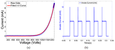
Figure 4. An example of CNT cathode performance in the x-ray tube. (a) The I-V curve of a CNT cathode shows the voltage needed to extract 7.5 mA of current. (b) The anode current waveforms for 5 mA current and 33 ms pulse width from 5 different CNT sources. The overshot signal at the beginning of each pulse was the step response of the switching electronics, which was not a real anode current overshoot.
Download figure:
Standard image High-resolution image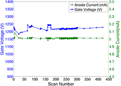
Figure 5. Stability measurement of a CNT source over 400 scans during a 4 month period. The tube current (green dashed curve) was kept at 5 mA, the cathode-gate voltage (blue curve) barely changes in the test. The tube current fluctuation is less than 2% over the 400 scans, and no significant degradation of cathode-gate voltage was observed.
Download figure:
Standard image High-resolution imageThe source-to-source consistency for all 75 CNT x-ray sources was evaluated. The gate voltage needed to generate 5 mA tube current for each source was measured and is plotted in figure 6. All 75 sources output the desired current. The difference between the highest and lowest cathode-gate voltage for 5 mA tube current is approximately 400 V, which was readily compensated for by the control electronics. The source-to-source output consistency in one scan was also evaluated. Figure 7 shows the anode current from each source in a single tomosynthesis scan using 32 CNT x-ray sources. The results show that the CNT source array can output 5 mA anode current consistently from source to source, within 0.3% accuracy. For all the images acquired in this study, all sources were set to output 5 mA tube current. By changing the pulse width (in ms) of each source was on, the x-ray output (in mAs) for each projection image was easily controlled.

Figure 6. Cathode-gate voltages needed to generate 5 mA tube current from each cathode. All 75 CNT cathodes can generate the desired current, with a small variation in voltage from cathode to cathode. The average voltage needed is 1240 V. The P00 refers to the central beam source, while the P and N notate positive and negative locations of the source relative to the central beam, respectively.
Download figure:
Standard image High-resolution image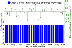
Figure 7. Summary of anode current in a short tomosynthesis scan using 32 sources and the relative difference to the average anode current. The CNT source array consistently output 5 mA from source to source with relative difference within 0.3%.
Download figure:
Standard image High-resolution image3.2. Focal spot size
The source array used in the study was designed to have an anisotropic focal spot shape, as it was originally designed for non-medical applications. Figure 8(a) shows the pinhole image from a source. The magnification factor of the pinhole was calculated based on the magnification in size of the pinhole assembly. The intensity profile of the focal spot was measured, normalized, and fitted into a 2D Gaussian distribution, as shown in figure 8(b). The intensity was closely matched to a 2D Gaussian distribution, with a coefficient of determination (R2) of 0.9923, which agrees with the simulation results using electrical optics simulation model from our lab (Sultana et al 2010). The FWHM of the intensity profile was used as the focal spot size. Figure 9 shows a summary of the measured focal spot size of 5 sources in the source array and the relative difference to the average value. The FSSx refers to the focal spot size along the scanning direction (x-direction), while the FSSy is the focal spot size perpendicular to the scanning direction (y-direction). The measurement results show the focal spot size is consistent from source to source within 4% relative error, with an average FWHM of 2.5 × 0.5 mm, which agrees with the designed value for this particular source array.
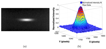
Figure 8. Focal spot measurement using a pinhole. (a) shows the a typical pinhole image acquired at 80 kVp and 5 mA. The pinhole was 400 µm in diameter and 2 mm in thickness. (b) shows the normalized intensity and the 2D Gaussian fit of the focal spot distribution.
Download figure:
Standard image High-resolution image
Figure 9. Summary of the focal spot size measurement of 5 sources in the source array. The average focal spot size was measured as 2.5 × 0.5 mm. The results show a good source-to-source consistency, as the relative difference is less than 4%.
Download figure:
Standard image High-resolution image3.3. Beam quality
The first HVL of the beam was measured to evaluate the beam quality. The first HVL was determined to be 3 mm at 80 kVp for this source array with 0.8 mm aluminum additional filtration, which comply with the regulatory minimum of 2.9 mm aluminum at 80 kVp (21CFR1020.30 2013).
3.4. Radiation dose
The incident air kerma at 100 cm from the focal spot was measured using the dosimeter at different tube mAs at 80 kVp. The tube output varied from 0.1 to 0.5 mAs. For each mAs setting, three measurements were made. Figure 10 plots the relationship between the incident air kerma and the mAs at 100 cm from the central source of the source array at 80 kVp. The measurements show a linear increase with the anode output mAs, as expected. The air kerma reading per mAs at 100 cm was measured to be 74.47 μGy mAs−1.
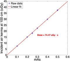
Figure 10. Experimentally measured relation between the incident air kerma at 100 cm from focal spot and x-ray tube output (mAs). The air kerma is linear to the anode output. The incident air kerma per mAs at 100 cm was measured as 74.47 μGy mAs−1.
Download figure:
Standard image High-resolution image3.5. System MTF and ASF
Projection images of the cross wire phantom were acquired at 80 kVp and 0.6 mAs per projection. The images were reconstructed using the RTT software into a tomosynthesis dataset with a 1 mm distance between slices. Figure 11(a) shows a reconstructed slice, where the crossed wires were focused. The MTF and ASF were studied for three imaging configurations with angular coverages, relative to the center of the detector, of 11.6°, 23° and 34°. For each imaging geometry, 29 projection images were used in reconstruction, with 0.4°, 0.8° and 1.2° angular spacing between each projection, respectively. Three randomly chosen regions across the perpendicular wire, as illustrated in the region outlined by a red box, were used as ROIs to measure the ASF. The average pixel value of the wire in the ROI and the background were measured for each slice and averaged to calculate the ASF. Figure 11(b) shows the LSF of the horizontal tungsten wire and the Gaussian-fitted LSF for the 34° imaging geometry. The MTF curves for both horizontal (x-direction) and vertical (y-direction) directions with the same imaging geometry are plotted in figure 11(c). The 10% cutoff of the MTF yields a spatial frequency of 1.5 cycles mm−1 and 3.2 cycles mm−1 for the x and y directions respectively. Figure 11(d) shows the ASF and the Gaussian-fitted ASF of the system as a function of depth (z-direction) for the 34° dataset. The in-depth (z-direction) resolution of the system, as measured by the FWHM of the ASF, was 5.2 mm.

Figure 11. (a) A reconstructed cross wire phantom in the plane of focus with an angular coverage of 34°. The region outlined by the red box illustrates one randomly selected ROI used to calculate the ASF. (b) The LSF of the horizontal tungsten wire and the Gaussian-fitted LSF from the 34° angular coverage dataset. (c) The MTFs of the system in both x (1.5 cycles mm−1) and y (3.2 cycles mm−1) directions for the 34° dataset. (d) The ASF of the system measured in the 34° dataset. The measured FWHM of the ASF indicates a 5.2 mm z-axis resolution.
Download figure:
Standard image High-resolution imageTable 1 lists the results of system MTF and ASF calculations for all three imaging configurations. The asymmetric MTF in the x and y directions is due to the anisotropic focal spot size in this particular CNT x-ray tube. The smaller focal spot size in y-direction results in a better MTF than in the x-direction. As shown in the table, the MTF in both the x and y directions remains essentially the same as the angular coverage increases from 11.6° to 34°, while the ASF improves greatly as the angular coverage increases.
Table 1. The experimentally measured MTF and ASF of the bench-top chest tomosynthesis system for three different angular spans. MTFx refers to direction parallel to the scanning direction, and MTFy refers to the perpendicular direction.
| Angular span | MTFx [cycles/mm] | MTFy [cycles/mm] | FWHM of ASF [mm] |
|---|---|---|---|
| 11.6° | 1.7 | 3.4 | 9.5 |
| 23° | 1.6 | 3.2 | 5.8 |
| 34° | 1.5 | 3.2 | 5.2 |
3.6. Phantom imaging
Projection images of the anthropomorphic chest phantom were acquired and reconstructed using RTT for image quality assessments. Tomosynthesis images with the same imaging dose but different angular spans were reconstructed and compared. Three datasets, each acquired using 29 projections at 110 cm SID and 80 kVp and 0.6 mAs per projection, were captured with angular spans of 11.6°, 23° and 34°. For each projection, 0.6 mAs results in approximately 62.3 µGy incident air kerma per projection view at the patient entrance plane, which is 25 cm in front of the detector. The dose per projection is more than sufficient for the typical dose of projection view reported in clinical DCT systems (Dobbins et al 2008, Sabol 2009). Three tomosynthesis slices from these datasets, focused at the same plane, are shown in figures 12(a)–(c), respectively. Tomosynthesis slices from all three configurations at another depth are shown in figures 12(d)–(f) as well. All reconstructed images clearly show the airways and detailed pulmonary vascular structures in the physical phantom. As the angular coverage increases, the artifacts from out-of-focus objects are reduced. At 11.6° angular span, ribs out of the focal plane can be seen in the slice, while at 23° and 34°, the visibility of these out-of-focus ribs is reduced. This is due to the improved in-depth resolution from increased angular span, as shown in the ASF measurement above. However, as the angular coverage increases, the angular step between projection images increases as well, resulting in ripple artifacts due to under sampling of the angular range (Deller et al 2007, Machida et al 2010). These ripple artifacts are caused by the high contrast objects (i.e. ribs) far outside the imaging plane that are not sufficiently blurred.
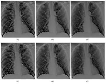
Figure 12. (a) and (d) show two slices at different depth (separate by 2.4 cm) reconstructed from 29 projection images acquired over 11.6°, (b) and (e), and (c) and (f) show the same slices reconstructed with same number of projection images but with 23° and 34° angular coverage, respectively. All three sets of images were acquired at the same total dose. It can be seen that the wider the angular coverage the lesser is the out of plan tomo artifact (such as those from the rib cage), due to improved in-depth resolution.
Download figure:
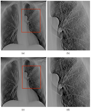
Standard image High-resolution imageTwo sets of tomosynthesis images, both covering the same 34° angular span and acquired with same total mAs, but with different numbers of projection images, were compared. Figure 13(a) shows a slice reconstructed with 32 projections covering 34°, acquired at 80 kVp and 0.6 mAs, while figure 13(c) shows the same slice reconstructed with 85 projections over the same angular span. Increasing the number of projections results in reduced ripple artifacts as shown magnified in figures 13(b) and (d), corresponding to the region boxed in red in figures 13(a) and (c), respectively. At the same angular coverage, more projection views decreases the angular step between projection views and reduces the under sampling of the sharp edges.
Figure 13. (a) shows a slice reconstructed with 29 projections over 34° angular span, while (c) shows the same slice reconstructed with 85 projections over the same angular span. As shown in the zoomed in region, outlined with a red box in (b) and (d), it can be seen that the ripple artifacts decreased when the number of projection images is increased. The two sets of images were acquired at the same total dose.
Download figure:
Standard image High-resolution image
4. Discussions
In this study, a bench-top DCT system was constructed and used to investigate the feasibility of a stationary DCT using a spatially distributed CNT x-ray source array. One of the key questions investigated was whether the CNT x-ray source array is capable of generating sufficient x-ray output for chest tomosynthesis. Projection images in current commercial DCT systems are typically acquired at 120 kVp and 180 cm SID. The tube output (mAs) is usually derived using automatic exposure control (AEC) from a scout view image (Sabol 2009, Båth et al 2010, Svalkvist et al 2010b, Terzi et al 2013). For instance, the GE VolumRAD DCT system multiply the mAs of scout view by 10, and uniformly distribute the derived mAs into 60 projection views. (Sabol 2009) The scout view is using standard PA CXR technique. Sabol calculated the mean technique of 1.9 mAs and 0.1 mGy incident air kerma for the standard PA CXR used in clinic from 294 adult cases (Sabol 2009). Based on the method to derive tomosynthesis radiographic technique from the scout view, the mean tomosynthesis technique is 0.32 mAs and 16.7 μGy incident air kerma per projection, where the SID is 180 cm and the incident air kerma was measured 25 cm in front of the detector (Sabol 2009). The incident air kerma is a more reliable reference since the tube output in mAs used also depends on the kVp, tube filtration, and SID. For the CNT source array used in this study, the incident air kerma per mAs at 100 cm was measured as 74.47 μGy mAs−1 at 80 kVp. The phantom images in this study were acquired at 0.6 mAs per projection. Using this technique, assuming an average-sized patient with a chest thickness of 25 cm and extending the s-DCT SID to 180 cm as current systems, the incident air kerma is scaled to 18.6 uGy at the patient entrance plane (155 cm from source), which is higher than the mean incident air kerma per projection in the tomosynthesis technique. With larger patient, the mAs per projection needs to be increased accordingly. Therefore, the x-ray output from CNT source array in this s-DCT system is comparable to current clinical tomosynthesis systems. All 75 CNT sources in the tube can be operated stably at this condition with reasonable source-to-source consistency in the cathode-gate voltage and focal spot size.
The x-ray source array was operated at 80 kVp in this study because that was the maximum design specification for the specific tube, which is why this study was done at a lower energy than the energy used in commercial chest tomosynthesis systems (typically 120 kVp). However, CNT x-ray source arrays using the same technology with energies up to 160 kVp, with comparable and higher power output, are now available for other imaging applications from XinRay Systems (Gonzales et al 2013). Future plans include designing and building a dedicated source array for chest tomosynthesis for higher x-ray energies, the feasibility of which has been demonstrated through the 160 kVp source array developed at XinRay Systems.
This particular model of CNT source array has an elongated focal spot size of 2.5 × 0.5 mm FWHM by design, as opposed to the isotropic shape found in most commercial DR systems (0.6–1.2 mm nominal size) (Dobbins and McAdams 2009, Svalkvist et al 2011, Quaia et al 2012). The anisotropic focal spot leads to asymmetric system MTF values in this system. The shape of the focal spot is determined by the geometry of the CNT cathode and the focusing electron optics design. Smaller isotropic focal spots can be achieved using a different electron optics, as demonstrated in the CNT source array designed for breast tomosynthesis (Qian et al 2012). The focal spot size and the maximum tube power is a tradeoff, which needs to be considered when designing a dedicated source array for chest tomosynthesis. A detailed anode heat simulation is needed to determine the optimum focal spot size based on the anode heat capability (Shan et al 2012). For instance, the tungsten anode can withstand 1.1 kW power safely in a 0.6 mm × 0.6 mm effective focal spot size during a 250 ms pulse according to simulation (Shan et al 2012, Qian et al 2012). If the tube operates at 120 kVp, the source array can be safely operated at 9 mA tube current. Given the performance of this tube, a slight reduction of the focal spot area is not expected to affect the ability to generate the x-ray output needed for chest tomosynthesis.
Due to the short length of the source array used in this feasibility study, the phantom and the detector were translated to mimic different imaging configurations. A longer x-ray source array covering the entire angular range can be manufactured with this technology. Preliminary results show that as the angular range of the image acquisition increases, the system in-plane resolution (system MTF) remains the same, while the in-depth resolution (FWHM of the ASF) improves greatly. These findings agree with previous studies on imaging parameters of tomosynthesis, using both stationary source array and conventional moving source commercial systems (Deller et al 2007, Machida et al 2010, Tucker et al 2013). The system MTF, corresponding to the direction with shorter focal spot size, resulted an in-plane resolution up to 3.4 cycles mm−1 at 10% MTF, which is comparable to the 3.5 cycles mm−1 at 10% MTF in GE VolumeRAD system and 3 cycles mm−1 at 10% MTF in Shimadzu SONIALVISION tomosynthesis systems (Flynn et al 2007, Svalkvist et al 2010a, Svalkvist 2011, Flynn 2012). Further studies will be focused on other quantifiable physical characteristics, such as contrast and signal difference to noise ratio (SdNR), as well as image quality of anthropomorphic phantoms to determine the optimal imaging configuration and the design of the dedicated source array. Moreover, the flexibility in the spatial configuration of the individual CNT sources allows new tomosynthesis imaging geometries, beyond the linear scanning mode, which are mechanically challenging for conventional systems. These novel imaging geometries may improve image in-depth resolution, and reduce the image artifacts. A systematic investigation and evaluation of the effects of imaging acquisition geometry and parameters on image quality in the s-DCT system will be performed and reported in the future.
In this study, anti-scatter grid was not used as in clinic settings normally, as the main purposes were investigating the feasibility of s-DCT and system requirements for CNT source arrays. The authors acknowledge the importance of scatter reduction in chest imaging and will explore techniques for scatter correction in future. For the s-DCT system using linear source array, conventional focusing anti-scatter grid with matching focal length can be used to reduce the scatter signal in the images. Besides the anti-scatter grid, other scatter reduction technique will also be studied (Inscoe et al 2013).
To sum up, this feasibility study was performed using a CNT x-ray source array that was originally designed for a non-medical application. As such, the technical specifications of the source are different from the x-ray tube used in commercial chest imaging systems including relatively low tube energy (kVp) and anisotropic focal spots. However, these differences do not impact the conclusions of this study. The s-DCT system reported in this paper is not the final system that would be for clinical use. One of the purposes of this study is to find the system requirements for stationary chest tomosynthesis. Based on the results obtained so far, a dedicated source array for chest tomosynthesis with improved design and system performance is under development. The source array will be designed with longer tube length to achieve optimized imaging configurations, higher operating kVp, isotropic and smaller focal spots, and higher tube current output that allows for fast image acquisition. Future studies that compare s-DCT with a dedicated source array to the commercial DCT systems will be conducted and reported.
5. Conclusion
A bench-top proof-of-concept stationary chest tomosynthesis system using a distributed CNT x-ray source array was constructed and evaluated. The tube characterization showed that the tube is capable of delivering adequate x-ray output as used in conventional chest tomosynthesis systems. System MTF and ASF results showed wider angular coverages can improve the system in-depth resolution, without impact on the in-plane resolution. The preliminary results obtained suggest that stationary chest tomosynthesis using a CNT source array is feasible. A next generation s-DCT system with dedicated source array for chest tomosynthesis is under development.
Acknowledgments
This work was sponsored by Carestream Health Inc., Rochester, NY. The authors would like to thank Christy R Inscoe of UNC-Chapel Hill for assistance with the project and Dr Houman Jafari (XinRay Systems Inc.) for technical support.