
Abstract
C-arm cone-beam CT (CBCT) can provide intraoperative 3D imaging capability for surgical guidance, but workflow and radiation dose are the significant barriers to broad utilization. One main reason is that each 3D image acquisition requires a complete scan with a full radiation dose to present a completely new 3D image every time. In this paper, we propose to utilize patient-specific CT or CBCT as prior knowledge to accurately reconstruct the aspects of the region that have changed by the surgical procedure from only a sparse set of x-rays. The proposed methods consist of a 3D–2D registration between the prior volume and a sparse set of intraoperative x-rays, creating digitally reconstructed radiographs (DRRs) from the registered prior volume, computing difference images by subtracting DRRs from the intraoperative x-rays, a penalized likelihood reconstruction of the volume of change (VOC) from the difference images, and finally a fusion of VOC reconstruction with the prior volume to visualize the entire surgical field. When the surgical changes are local and relatively small, the VOC reconstruction involves only a small volume size and a small number of projections, allowing less computation and lower radiation dose than is needed to reconstruct the entire surgical field. We applied this approach to sacroplasty phantom data obtained from a CBCT test bench and vertebroplasty data with a fresh cadaver acquired from a C-arm CBCT system with a flat-panel detector. The VOCs were reconstructed from a varying number of images (10–66 images) and compared to the CBCT ground truth using four different metrics (mean squared error, correlation coefficient, structural similarity index and perceptual difference model). The results show promising reconstruction quality with structural similarity to the ground truth close to 1 even when only 15–20 images were used, allowing dose reduction by the factor of 10–20.
Export citation and abstract BibTeX RIS
1. Introduction
Minimally invasive surgery is becoming more popular with the support of advanced surgical techniques and imaging technologies, allowing for less blood loss, reduced postoperative pain, and shorter hospital stay and recovery time. Current minimally invasive surgeries are carried out with the aid of intraoperative imaging to visualize the surgical field during the procedure (Cleary and Peters 2010, Mathis and Golovac 2010). In particular, the accurate placement of instrumentation and the efficacy of the surgical approach have been the key issue in all types of image-guided surgeries, and tremendous efforts were made to minimize the surgical trauma and maximize the surgical outcomes while sparing the vital structures near the target. Therefore, in many image-guided surgeries, preoperative CT or MR is commonly used for diagnosis and surgical planning, and 2D fluoroscopy has been one of the preferred methods of evaluating these changes during the surgery due to the accessibility, real-time and cost-effective nature of these imaging systems. However, intraoperative evaluation of the true 3D positions and shapes of surgical tools and implants is still very challenging, which sometimes leads to critical failures such as misplacement of instrumentation. Therefore, there is a vigorous trend towards the use of 3D C-arm cone-beam CT (CBCT) in image-guided interventions to intraoperatively obtain 3D views of the surgical field, maximize safety and minimize radiation exposure. Furthermore, powerful computer and tracking systems combined with 3D imaging techniques provide surgical navigation capabilities with a real-time visualization of the patient anatomy along with surgical tools.
In state-of-the-art navigation systems, specialized instruments are tracked by an external tracker and their 3D positions are registered and overlaid to the surgical volume to guide the surgeon. However, the relative position of any instrumentation to the patient anatomy varies as the surgical procedure progresses and surgical changes imparted to the patient anatomy during the surgery cannot be accurately evaluated unless the surgical field is periodically updated in the course of the surgery, which in turn significantly increases radiation dose and impedes workflow. These limitations represent significant impediments to successful surgical outcomes.
Radiation exposure to the patient and surgical staff is also of great concern in image-guided surgeries (Giordano et al 2009). Surgeons and surgical staff are repeatedly exposed although the expected yearly doses are less than the maximum recommended doses (Singer 2005). For example, surgeons in minimally invasive spine surgeries work close to and often in the x-ray beam, having 10–20 times more dose than other orthopaedic surgeons (Rampersaud et al 2000). Therefore, dose reduction in image-guided surgeries is especially significant. Several comparison studies show that overall radiation dose reduction is possible by using image-guidance with navigation technique compared to conventional surgeries (Gebhard et al 2003, 2006, Slomczykowski et al 1999, Tjardes et al 2010), but repeated intraoperative scans for validating the surgical procedure will significantly increase dose.
In current image-guided surgeries, CT or MR is typically obtained for diagnosis, surgical planning and navigation (Schoenfeld et al 2010, Muchow et al 2008). Typically, intraoperative imaging for various image-guided surgeries such as orthopaedic, spinal and vascular surgeries is carried out using C-arms that allow both real-time fluoroscopy and rotational CBCT (Nolte et al 2000). Biplanar fluoroscopy allows more rapid visualization of AP and LAT view (Mathis and Golovac 2010), and CT is also occasionally used for procedures that involve complex geometries and/or require detailed soft-tissue visibility (Haberland et al 2000). However, these systems are expensive, require dedicated suites and sometimes require alteration of the surgical procedure, thus yielding poorer workflow than C-arms. Recent advancement of flat-panel detector (FPD) technology allows high-quality mobile C-arm CBCT for intraoperative imaging (Siewerdsen et al 2009). FPD-based isocentric mobile C-arms provide 3D imaging with image quality sufficient for a broad spectrum of surgical applications (e.g. orthopaedic, spine, skull base and thoracic surgery) with greater mobility at lower cost compared to fixed base C-arm or CT. These systems exhibit larger fields of view (FOV), broader dynamic range, higher spatial resolution, improved soft-tissue visibility and reduced image distortion in comparison to C-arms using an x-ray image intensifier. In particular, the surgical volume can be imaged in CBCT at the beginning of the surgical process and an immediate registration of the instrument-tracking system to the surgical field can be performed (Siewerdsen et al 2009, Uneri et al 2011, Schafer et al 2011).
Modern motorized isocentric C-arms are capable of reconstructing a 3D FOV using filtered backprojection (FBP) (Feldkamp et al 1984) from data acquired over a circular source sweep of at least 180° + fan angle, often called short-scan, and some algorithms can handle even less than a short-scan data (Yu and Wang 2004, Pack et al 2005, Zou et al 2005, Noo et al 2002). Although data truncation due to small detector FOV and limited-angular sweep were the main limitations of the C-arm CBCT applications, various feasible solutions have been proposed. For example, truncation issue can be resolved by using sinogram completion (Lewitt 1979, Hsieh et al 2004, Chityala et al 2005, Zamyatin and Nakanishi 2007), differentiated backprojection approaches (Pack et al 2005, Zou et al 2005, Noo et al 2002, Pan et al 2005, Defrise et al 2006, Kudo et al 2008), region-of-interest imaging and interior tomography approaches (Yu and Wang 2009, Yang et al 2010, Taguchi et al 2011, Xu et al 2011), and a hybrid approach where a patient-specific prior volume or statistical atlas is injected in order to compensate for missing information on the data (Sadowsky et al 2009, 2011). The limited-angle problem has also been addressed with limited success using iterative reconstructions and differentiated backprojection methods (LaRoque et al 2008, Sidky and Pan 2008, Noo et al 2002, Pan et al 2005, Defrise et al 2006, Kudo et al 2008) and a hybrid approach (Sadowsky et al 2009, 2011), and also the next generation mobile C-arms are capable of ∼180° rotation or more, yielding a fairly small limited-angle reconstruction artefact for interventional use (Siewerdsen et al 2009).
However, radiation dose and workflow still remain unresolved challenges that inhibit intraoperative C-arm CBCT from being widely utilized in image-guided minimally invasive surgeries. This is partly because each 3D image acquisition requires a complete scan that imparts a full radiation dose. The usual means of 3D reconstruction of FBP does not utilize information from prior scans and presents the surgeon with a completely new 3D image every time. The volume-of-change (VOC) reconstruction method proposed in this paper attempts to reconstruct only the aspects of the anatomy that have been altered since the previous acquisition and does so from a minimal set of new projection data. It therefore opens a potentially significant opportunity to address challenges in dose and workflow problems in image-guided surgeries. The VOC reconstruction is realized by fully utilizing patient-specific prior knowledge and combining statistical iterative reconstruction techniques with a compressed sensing (CS) regularization (Candes et al 2006, Sidky and Pan 2008, Tang et al 2009, Jia et al 2010).
This paper proposes a new strategy to achieve both high-quality and low-dose intraoperative imaging. This is possible by extensively utilizing prior knowledge of the patient anatomy, which can reduce reliance on fluoroscopy, augment full 3D acquisitions, and complement the overall intraoperative imaging and navigation system. We propose to reconstruct the region of surgical change accurately by integrating patient-specific prior information into intraoperative C-arm CBCT for low-dose, high-quality 3D imaging in image-guided surgeries. The proposed approach involves patient-specific prior information such as preoperative CT or CBCT, sparse intraoperative CBCT scan, 3D–2D registration between the prior volume and the intraoperative scans, difference image computation, and VOC reconstruction from the sparse set of difference images followed by a fusion of the reconstructed VOC with the prior volume. A sparse scan is realized by taking larger angular steps between each projection image over the scan arc, for example, 15 projections uniformly spread over a 180° + fan angle. A sparse scan offers a means to reduce radiation dose by reducing the number of projections. An alternative means of dose reduction is to keep the number of projections constant while instead reducing the mAs per projection. The sparse-scan scenario offers the advantage of a smaller projection dataset, thereby reducing computational load in iterative reconstruction methods as considered below, but introduces a challenge of view aliasing from low angular sampling. The low mAs scenario provides reduced view aliasing but entails a large projection dataset (i.e. larger computational load) and is ultimately limited in dose reduction capability by the electronic noise of the detector. The sparse-scan scenario considered in the experiments reported below is well suited to fast, low-dose image updates in image-guided interventions. When the size of the surgical change is small, the changed region can be localized from the surgical plan and the VOC reconstruction may involve only a small volume of interest (VOI), allowing less computation than is needed to reconstruct the entire surgical field. (Note that we achieve dose reduction by using the sparse-scan approach, not by taking advantage of the small size of the VOC that is reconstructed. The latter approach is further discussed in section 9.2.) Figure 1 shows the VOC reconstruction workflow. The proposed VOC reconstruction approach was tested in a series of physical experiments, including a simulated sacroplasty with a dry cadaveric bone and vertebroplasty in a cadaveric torso. The visually promising reconstruction results were quantitatively evaluated using metrics of accuracy and perceptual difference from images acquired from a full projection dataset.
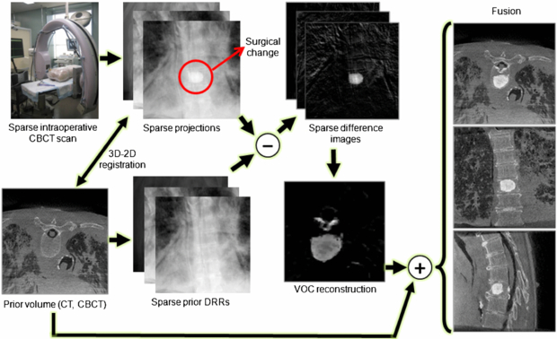
Figure 1. VOC reconstruction workflow. The surgical change illustrated is an injection of bone cement in a thoracic vertebra.
Download figure:
Standard image2. Incorporation of patient-specific knowledge in 3D reconstruction
2.1. Patient-specific prior knowledge
Since for many surgical scenarios, the changes imparted to the patient in any given step of the procedure may be local and relatively small, there is a significant amount of redundant information, i.e. unchanged patient anatomy, between repeated scans. This implies that, if we know how to relate the already-known information to new information in the current scan, we can highlight the regional changes and restore them from a much smaller amount of data than is needed to reconstruct an entirely new image volume, which leads us to extensively utilize available patient-specific prior knowledge for intraoperative 3D reconstructions. In this paper, we use a preoperative CT or CBCT scan as patient-specific prior knowledge to augment sparse-scan data obtained during surgery. In particular, the prior anatomical model is used to generate difference projection images, ideally, showing surgical changes only, thus connecting patient-specific prior knowledge to high-quality VOC reconstructions. Specifically, instead of performing a complete CBCT scan that involves a full radiation dose, the VOC approach attempts to reconstruct only the aspects of the region that have changed since the previous scan from a sparse set of projections. Only new information, i.e. the VOC, is reconstructed, and the result may be fused with the prior volume, to present a complete and up-to-date view of the surgical field.
2.2. 3D–2D registration and difference images
To fully utilize the information available from the prior volume, an accurate 3D–2D registration between the prior volume and the observed projections is necessary. Once a sparse set of intraoperative projections are obtained during the surgery, the 3D prior volume is registered to them. Since patient anatomy contains both structures that deform such as soft tissue, and ones that remain rigid such as bone, between scans, we first obtain a bone-only prior volume by thresholding. During the registration process, digitally reconstructed radiographs (DRRs) of the prior volume are repeatedly generated and compared to the selected sparse subset of 2D intraoperative projections. To measure data similarity between DRRs and the observed projections, we used the gradient difference similarity metric because of its known robustness to the slowly-varying soft tissue background in the projections and local data inconsistency introduced by surgical tools and implants (Penney et al 1998). The gradient difference of two images is computed as

where Iproj is the observed x-ray projection, IDRR is the generated DRR, IVdiff and IHdiff are vertical and horizontal gradient differences, respectively, s is a scaling factor that considers the intensity difference between the x-ray image and the DRR, and Av and Ah are regularizing constants, which in our experiments were the variance of the respective gradient x-ray image. Since a new set of DRRs has to be created at every iteration during the optimization, Siddon's forward projection method (Siddon 1985) was implemented on GPU for generating DRRs. The registration was optimized for pose by using the downhill simplex method (Nelder and Mead 1965).
Once the prior volume is registered to the observed 2D projections, we compute a series of difference images that highlight surgical changes. The idea of computing difference images to highlight the structure of interest is not new, and has been used in digital subtraction angiography (Heautot et al 1998, Bidaut et al 1998, Anxionnat et al 2001) where contrast-enhanced vascular structures are highlighted by subtracting mask images obtained prior to the contrast agent injection at the same image poses. Since such mask images are not generally available in most surgical procedures, we instead use the patient-specific prior volume to create DRRs that are used as mask images, thus computing difference images by subtracting DRRs from the intraoperative x-rays.
3. VOC reconstruction
3.1. Statistical imaging model and penalized likelihood reconstruction
In transmission tomography, the measurement of x-ray photons after being attenuated by an object under a monochromatic x-ray assumption can be approximated as

where Ii0 is the number of unattenuated photons, µ is the digitized linear attenuation map of the object, A is the system matrix, and [Aμ]i is the line integral of the linear attenuation map µ measured at the detector element i. Assuming an ideal detector, each measurement yi at the detector element i is independent of measurement in neighbouring pixels and follows a Poisson distribution with the expectation value of  . Under this assumption, the joint probability of this measurement is derived as

and the corresponding negative log-likelihood is given by

ignoring the constant term. Direct minimization of equation (5) yields the maximum likelihood (ML) estimate  which is very noisy. Alternatively, a penalized likelihood (PL) or a maximum a posteriori method regularizes the problem by applying roughness penalty to the objective function, thus reducing the noise. In this approach, the following PL objective function modified from equation (5) is minimized:

where R(μ) is a smoothness prior and β controls the relative contribution of the likelihood and the prior terms. In order to penalize difference in the neighbouring pixels and preserve edges, we typically use the following penalty:

where Ψ is the spatial gradient operator and δ is a small constant. This penalty is similar to the 1-norm to the spatial gradient of the image estimate (μ) and also Geman prior (Geman and Reynolds 1992, Geman et al 1992) which is closely related to the total variation (TV) norm (Tang et al 2009), but is differentiable everywhere.
It has been reported that this PL reconstruction with a proper choice of smoothness prior can provide an improved reconstruction compared to TV-based CS reconstruction (Tang et al 2009). In particular when the dose level is very low, TV-based CS reconstruction results in patchy images while mitigating streak artefacts, which could be harmful. Since our goal is to achieve low-dose and high-contrast VOC reconstruction, the PL approach is an appropriate choice.
3.2. VOC reconstruction
In the VOC reconstruction method, we have two measurements; one is the projections ( ) obtained during the surgical procedure and the other is the DRRs (
 generated from the registered prior volume. The measured x-ray image
  is created from the intraoperative patient anatomy (μintraop) that contains the regional change made by the surgical procedure, but the DRR is generated from the prior volume (μprior) that does not involve the surgical change. However, when we compute the difference between these two datasets (after taking the logarithm) assuming no registration error, the resulting difference can be considered as a projection of the difference between the intraoperative patient volume and the prior volume, i.e. μVOC = μintraop − μprior. Therefore, the difference projection can be described from equation (3) as

which is the projection of the change. Although the difference images can be described as above, the likelihood has changed because this difference image computation involves a nonlinear subtraction of Poisson random variables. However, due to the complexity of the nonlinear subtraction of Poisson random variables, we assume that it is approximately Poisson in this paper, and a more accurate noise model is currently under investigation. Under the Poisson approximation, μVOC can be estimated by minimizing the following objective function using the likelihood in equation (5) and the penalty in equation (7):

Once the VOC is reconstructed, we can recover the entire intraoperative volume by fusing the VOC reconstruction with the prior volume:

The PL estimation problem in equation (9) can be solved in various ways, and we used the ordered subset transmission tomography approach proposed by Erdogan and Fessler (1999).
4. Image quality assessment
To assess the image quality and accuracy of the VOC reconstruction, we compare it to ground truth defined as a CBCT reconstruction computed from the complete dataset (i.e. many projections acquired over a circular or semicircular arc reconstructed by FBP). We use a collection of similarity measures to elucidate the results quantitatively: mean squared error (MSE), correlation coefficient (CC), structural similarity index (SSIM) (Wang et al 2004) and perceptual difference model (PDM) (Salem et al 2002).
MSE and CC between two reconstructed volumes x = (x1,..., xn) and y = (y1,..., yn) are computed as


where  and
and  are the mean values of xi and yi, and σx and σy are the standard deviations of xi and yi, respectively.
The SSIM combines three similarity components; luminance (l), contrast (c) and structure (s), which are computed as


where C1, C2 and C3 are constants included to avoid instability. We used the same C1, C2 and C3 values as in Wang et al (2004). These three components are combined to form an overall SSIM as

We also used a PDM based on the difference between two images considering a human visual system model. The PDM metric consists of five sub-steps: luminance calibration, contrast sensitivity function, cortex filters, detection mechanisms and difference visualization. For the details of PDM, refer to Salem et al (2002). Since the human visual system model-based metric supports only 2D images, we compared each axial slice and computed an average PDM score of all the slices:

5. Phantom experiment
5.1. Image acquisition: CBCT test bench
An experimental x-ray bench that provides a precise and flexible platform for investigation of CBCT imaging performance was used for a phantom study. The bench consists of an x-ray tube (DU694 in an EA10 housing; Dunlee, Aurora, IL), a FPD (2048 × 1536 format 4030 CB detector with 0.194 mm pixel pitch and CsI:Tl converter; Varian Medical Systems, Salt Lake City, UT) and a motion control system (Compumotor 6k8 and Dynaserv G3 servo drive with a DR 1060B motor; Parker Hannifin, OH). The bench offers a wide range of source–detector motions and x-ray techniques, emulating a broad range of x-ray systems including C-arms with precise control and reproducibility of system geometry and a high degree of user control over the acquisition process. The phantom images were acquired at 100 kVp and 125 mA (500 mAs). Each image has the size of 1024 × 768 pixels with a pixel pitch of 0.388 mm after a 2 × 2 binning. The phantom imaging setup on the CBCT bench is shown in figure 2.

Figure 2. Phantom imaging setup on the CBCT test bench.
Download figure:
Standard image5.2. Sacroplasty
A sacroplasty was simulated on a dry cadaveric sacrum phantom without soft tissue. A preoperative full sweep CBCT scan (360 cone-beam projections over a 360° arc) was first acquired from which a CBCT volume (400 × 400 × 400 voxels with a voxel size of 0.5 × 0.5 × 0.5 mm3) was reconstructed as a prior volume. Bone cement (Spineplex, Stryker Spine, Allendale, NJ) was injected into the upper portion of the sacrum to create a surgical change. After the bone cement injection, another full sweep CBCT scan was performed, and different subsets of 15, 30, 45, 60 projections that were uniformly sampled over 180° among the full scan data were extracted to generate sparse post-injection scans. We placed six stainless steel beads on the sacral surface to ensure the registration and validate the VOC reconstruction method on an ideal case, i.e. with an accurate registration and using the same imaging system at the same x-ray energy. Once the prior volume was registered to the post-injection x-ray images using these six beads, DRRs were generated from the registered prior volume and subtracted from the post-injection x-ray images to create difference images. A series of VOCs (300 × 300 × 90 voxels with a voxel size of 0.5 × 0.5 × 0.5 mm3) were reconstructed from the different subsets of 15, 30, 45, 60 difference images by the PL reconstruction method with different β values.
To assess the VOC reconstruction quality, we also reconstructed a post-injection CBCT volume (400 × 400 × 400 voxels with a voxel size of 0.5 × 0.5 × 0.5 mm3) by using all 360 post-injection projections and computed a ground truth VOC by subtracting the prior CBCT volume from the post-injection CBCT volume. Since pure subtraction of two CBCT volumes yields noisy images of the change and the bone cement has uniform density, we applied a median filter to this subtracted volume to remove quantum noise while maintaining the overall shape and edge. We compared the sparse VOC reconstructions to this ground truth using the similarity metrics described in section 4.
6. Phantom experiment results
Since we used six beads for registering the CBCT prior volume to the post-injection x-ray projections and there is no soft tissue in the phantom, the registration was very accurate and the difference images clearly show the region of change while other structures are eliminated as shown in figure 3. The VOCs reconstructed from 15, 30, 45, 60 difference images by the PL reconstruction method with different β values (101–1010) were compared to the CBCT ground truth, and figure 4 shows the similarity measure plots as a function of β. It is observed that the reconstruction is noisier at lower β where the estimate is closer to ML estimate, but becomes smoother at higher β where the reconstruction is more regularized by the penalty. Since the shape and structure of the bone cement was not so complicated and the registration was accurate, the overall reconstruction quality was not degraded even when we reduced the number of images and the similarity plots show similar reconstruction performance regardless of the number of images. It is also observed from these plots that the overall reconstruction quality is lower at lower β because it is noisier, but is similarly good when β becomes large. Figure 5 shows an example of slice images of the VOC reconstruction computed from 15 projections after 100 iterations with β = 107 (chosen from figure 4) and its fusion with the prior volume. The reconstructed VOC with prior volume showed significantly reduced artefact compared to the FBP reconstruction (Feldkamp et al 1984) computed from the same 15 post-injection x-ray images.
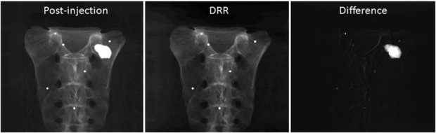
Figure 3. Example projection images (log-transformed). (Left) X-ray image after the bone cement injection. (Middle) DRR generated from the registered prior CBCT. (Right) Difference image computed by subtracting the DRR from the post-injection x-ray image.
Download figure:
Standard image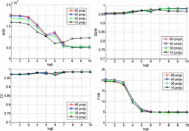
Figure 4. Similarity measures for different number of projections and β values.
Download figure:
Standard image
Figure 5. Axial, coronal and sagittal slice images of different reconstructions. (First column) VOC reconstruction computed from 15 projections over 180° (β = 107, 100 iterations). (Second column) Fusion of VOC reconstruction with the prior volume. The change is highlighted in red. (Third column) FBP reconstruction computed from 15 projections over 180°. (Fourth column) Post-injection CBCT reconstruction from 360 projections over 360°.
Download figure:
Standard image7. Cadaver experiments
7.1. Image acquisition: C-arm CBCT
A prototype FPD-based mobile C-arm for high-performance CBCT (C14, Siemens Medical Solutions, Erlangen, Germany) was used for imaging cadaver specimens during simulated vertebroplasty procedures. The C-arm is based on a Siemens Powermobil and employs a 30 × 30 cm2 CsI:TI FPD with an active matrix of 1536 × 1536 at 194 µm pixel size (PaxScan 3030+, Varian Imaging Products, Palo Alto, CA). The C-arm operated at the tube voltage of 120 kVp and current of 2.3 mA (230 mAs), and a total of 200 CBCT images were acquired over an angular range of 178°. Figure 6 shows the cadaver imaging setup.
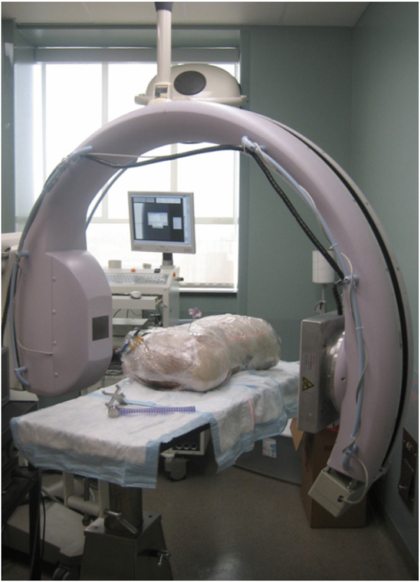
Figure 6. C-arm CBCT system and the cadaver experiment setup.
Download figure:
Standard image7.2. Thoracic vertebroplasty
Vertebroplasty was performed on a thoracic vertebra in a cadaver torso. A pre-injection C-arm CBCT scan was first performed to get 200 pre-injection x-ray projections over a 178° arc, from which a prior volume of 512 × 512 × 512 voxels with a voxel size of 0.2930 × 0.2930 × 0.2930 mm3 was reconstructed. A surgeon carefully injected bone cement (Confidence Spinal Cement, DePuySpine, Raynham, MA) into a thoracic vertebra without moving the cadaver torso so that the CBCT scan could be repeated on the same C-arm orbit at the same subject position. After the bone cement injection, a post-injection CBCT scan was performed to get 200 post-injection x-ray projections at the same poses as the pre-injection scan and a post-injection volume with the same volume and voxel sizes to the pre-injection volume was reconstructed. Since both the cadaver and the C-arm did not move between these two scans and the C-arm image acquisition was reproducible, we assumed that these two scans were registered. Therefore, difference images were computed by directly subtracting the pre-injection x-ray images from the corresponding post-injection x-ray images.
Among 200 difference images, we uniformly sampled subsets of 10, 20, 40, 66 projections to simulate sparse intraoperative scans. VOCs of 250 × 250 × 250 voxels with a voxel size of 0.2930 × 0.2930 × 0.2930 mm3 were reconstructed by the PL method from these difference images. The reconstructed VOCs were compared to a ground truth VOC that was computed by subtracting the pre-injection CBCT volume from the post-injection CBCT volume followed by the median filtering to remove quantum noise as we did for the phantom experiment.
7.3. Lumbar vertebroplasty
We have also performed vertebroplasty on a lumbar spine of the torso cadaver. In this case, the cadaver and the C-arm moved between the pre- and post-injection scans. A preoperative CT volume (512 × 512 × 232 voxels with a voxel size of 0.9062 × 0.9062 × 3.0 mm3) was first obtained before injecting the bone cement, and both pre- and post-injection C-arm CBCT scans were performed before and after the cement injection. In the post-injection scan, we obtained 200 projections over a 178° arc, from which we extracted 10, 20, 40, 66 projections to create sparse projections. Since the shape of the cadaver torso was maintained, rigid 3D–2D registrations between the prior CT and the pre- and post-injection x-ray projections were first computed. Difference images were computed by subtracting the DRRs of the registered CT from the post-injection x-ray images as described in section 2.2.
VOCs of 250 × 250 × 400 voxels were reconstructed from different image sets by the PL method, and merged with the prior volume to show a full surgical field. A ground truth VOC was computed by subtracting pre-injection CBCT volume from the post-injection CBCT volume (both have 512 × 512 × 512 voxels with a voxel size of 0.2930 × 0.2930 × 0.2930 mm3) followed by the median filtering, and the VOC reconstructions were compared to the ground truth.
8. Cadaver experiment results
8.1. Thoracic vertebroplasty
Figure 7 shows example images of the pre- and post-injection x-ray projections and the computed difference images. Since there was only negligible motion of the cadaver and the C-arm between these two scans, the difference image clearly shows the bone cement while other structures are eliminated. Note that this subtraction process is commonly used in digital subtraction angiography (Heautot et al 1998, Bidaut et al 1998, Anxionnat et al 2001). Similarity measures between the reconstructed VOCs and the ground truth for different β values are plotted in figure 8. Although there was noticeable reconstruction quality degradation when only 10 images were used, it was minor when 20, 40 and 66 images were used. Figure 9 shows example slice images of the VOC reconstruction computed from 20 projections and merged with the prior volume for β = 104 that was chosen based on the similarity measures shown in figure 8. Unlike the FBP reconstruction computed from the same 20 projections, both the surgical change including extravasation and the unchanged patient anatomy are clearly visible in the VOC reconstruction.
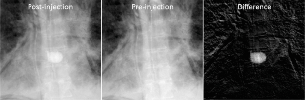
Figure 7. Example projection images (log-corrected). (Left) Post-injection x-ray image. (Middle) Pre-injection x-ray image. (Right) Difference image.
Download figure:
Standard image
Figure 8. Similarity measures for different number of projections and β values.
Download figure:
Standard image
Figure 9. Axial, coronal and sagittal slice images of different reconstructions. (First column) VOC reconstruction computed from 20 projections over 178° (β = 104, 100 iterations). (Second column) Fusion of VOC reconstruction with the prior volume. The change is highlighted in red. (Third column) FBP reconstruction computed from 20 projections over 178°. (Fourth column) Post-injection CBCT reconstruction from 200 projections over 178°.
Download figure:
Standard image8.2. Lumbar vertebroplasty
In the lumbar vertebroplasty case, a prior CT volume was used as a prior volume and registered to the post-injection CBCT x-ray projections using the method in section 2.2. Figure 10 shows example images of the post-injection CBCT projections, DRR computed from the registered prior CT and the resulting difference image. Since the prior CT was rigidly registered to the CBCT projections, there are intensity mismatches especially in the soft tissue and air regions. Also DRR looks blurred compared to the post-injection x-ray image due to the low spatial resolution of the CT data. However, the bone cement is clearly highlighted in the difference image. Similarity measures between the reconstructed VOCs and the ground truth as a function of different β values are computed and plotted in figure 11. Similar to the thoracic vertebroplasty case, there were only minor reconstruction quality variations between 20 and 66 projections although image quality degradation was relatively large when only 10 projections were used. Figure 12 shows example slice images of the VOC reconstruction computed from 20 projections with β = 107 (chosen from the similarity measures shown in figure 11) and merged with the pre-injection CBCT prior volume. Both the surgical change and the background patient anatomy are clearly visible and the extravasation can be detected in the final VOC reconstruction although it is very hard to see the injected bone cement in relation to the patient anatomy in the FBP reconstruction from the same 20 post-injection x-ray images.
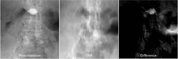
Figure 10. Example projections (log-corrected). (Left) Post-injection x-ray image. (Middle) DRR computed from the registered CT prior volume. (Right) Difference image.
Download figure:
Standard image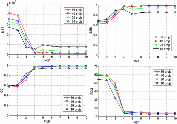
Figure 11. Similarity measures for different number of projections and β values.
Download figure:
Standard image
Figure 12. Axial, coronal and sagittal slice images of different reconstructions. (First column) VOC reconstruction computed from 20 projections over 178° (β = 107, 100 iterations). (Second column) Fusion of VOC reconstruction with the prior volume. The change is highlighted in red. (Third column) FBP reconstruction computed from 20 projections over 178°. (Fourth column) Post-injection CBCT reconstruction from 200 projections over 178°.
Download figure:
Standard image9. Discussion
We proposed a novel reconstruction approach, called VOC reconstruction, where patient-specific prior knowledge is utilized to accurately reconstruct the regions that have been changed by the surgical procedure from only a sparse set of projections for low-dose, high-quality imaging in image-guided surgery. We performed a series of preliminary studies in this paper, showing promising results, but the following issues are under consideration for our future research.
9.1. Prior volume
The key advantage of the proposed VOC reconstruction approach is that one can achieve low-dose, high-quality imaging as well as compensate for the truncation that is common in CBCT due to the small lateral FOV. Therefore, we assume that the prior volume has all the information of the patient anatomy except for the surgical change-–i.e. the prior volume is not truncated. This assumption is important because we subtract all redundant information in the prior volume from the intraoperative x-ray scan data to highlight the surgical change only. This difference image computation can be considered as a form of truncation compensation because the ray sum from all the non-changed patient anatomical structures will be subtracted in the projection domain and the resulting difference images therefore show only the changes without truncation. This is a reasonable assumption, since a non-truncated, patient-specific prior volume is often available in image-guided surgical procedures from the preoperative, diagnostic and/or planning images. CT is a very common preoperative imaging modality for image-guided orthopaedic/spine surgery and radiation therapy. For anatomical sites for which CBCT can be used to provide a non-truncated prior volume (e.g. head and neck imaging and/or CBCT data acquired from an offset-detector geometry), that image may also serve as a prior volume. As one can easily imagine, there are intensity inconsistencies between the DRRs created from the prior volume and the intraoperative x-ray projections at views for which the truncated anatomy is involved in DRR generation. Theoretically, the VOC reconstruction approach will reconstruct not only the changes made by the surgical procedure but also any difference between the current target volume and the prior volume. However, accurate reconstruction can be computed only when we consider both positive and negative intensity differences during the reconstruction, as discussed below in section 9.3. In this case, the full CBCT FOV must be reconstructed because the change will no longer be local but spread over the entire FOV.
9.2. Dose reduction
In this paper, we demonstrated the sparse-scan scenario to achieve low-dose imaging. This is a reasonable choice because we can simply reduce the radiation dose by reducing the number of projections and a sparse scan is known to be effectively handled by an iterative reconstruction technique with CS regularization. Another possible way of dose reduction is a reduced-dose scan where dose per projection is reduced. The reduced-dose scan can be better handled by the statistical reconstruction approach than conventional FBP or other iterative reconstruction techniques such as POCS or TV-based CS approach because the statistical approach takes into account the noise property in the observed image while others do not.
One may also achieve dose reduction by limiting the exposure to a small FOV (using, for example, dynamic collimation) when the exact target location is known (Heuscher and Noo 2011). This approach may require hardware changes such as collimators, beam filters and controller to dynamically change the FOV during the scan. Additionally, a smaller FOV may cause significant errors in 3D–2D registration of the prior volume to intraoperative x-ray projections due to the lack of common information between them. (Note that the prior volume does not reflect the surgical change.) Therefore, we focused the current work on the sparse-scan scenario in which the number of projections collected over a semicircular arc is significantly reduced, thus reducing the overall dose. The other dose reduction scenarios are areas of on-going research.
9.3. Noise model in the statistical reconstruction
We assumed that the noise in the difference image obeys a Poisson distribution, and enforced positivity constraints because the surgical change we considered here, i.e. bone cement, has larger linear attenuation coefficient than the patient anatomy. Although this is partly true in an ideal case where the 3D–2D registration between the prior volume and the observed x-rays is perfect, there exist both positive and negative changes in the difference images in reality due to registration errors. Even when the 3D–2D registration is perfect, the noise in the difference images does not obey a Poisson distribution although Poisson approximation shows reasonably good reconstruction. Therefore, further modification of the noise model and the constraints may be needed to improve reconstruction and allow not only positive changes but also negative changes, which is our future research. For example, one may use the Gaussian noise model without positivity constraints or experimentally estimate the noise distribution rather than assuming Poisson to handle this issue.
9.4. 3D–2D registration
In our experiments, we only performed 3D–2D rigid registration because the target was not moved or significantly deformed between the prior scan and the intraoperative scans. However, in reality, there could be a considerable amount of soft-tissue deformation between the prior scans (usually preoperative CT scan or initial intraoperative CBCT scan) and the intraoperative scans. Therefore, an accurate 3D–2D deformable registration might be necessary to compute accurate difference images showing surgical change only. However, the 3D–2D deformable registration problem is very challenging and is an active area of research that deserves separate papers. One viable approach we can consider for image-guided surgery applications is to perform 3D–3D deformable registration as soon as we get an initial intraoperative CBCT volume for visualizing the surgical field and registering surgical tools within a surgical navigation system at the beginning of the surgery (Nithiananthan et al 2011, Uneri et al 2011). Since the patient does not move significantly during the surgical procedure, the successive CBCT scans will already be roughly registered to the initial CBCT volume as well as the prior images. Therefore, the successive 3D–2D registration problem will be relatively easier than direct registration of the 3D prior volume to 2D intraoperative scans.
9.5. Computation time
Our registration and reconstruction algorithms were implemented on a combination of Matlab and C++ with the forward and backprojection implemented on a GPU. Since they were not optimized for the best performance, the overall process still requires significant amount of computation time (∼10 min for 10–66 projections and volume sizes shown in our experiments). We believe that this can be significantly improved by setting the VOI more tighter using the surgical plan (note that the VOIs in our experiments are large) and designing the algorithm for GPU and optimizing the code using C++, which is under development. For example, Jia et al (2010) reported that a CBCT volume can be reconstructed using a TV-based compressed sensing reconstruction from 20–40 projections in a few minutes using their GPU-friendly version of forward–backward splitting algorithm.
10. Conclusions
The key benefit surgeons expect from image-guidance in minimally invasive surgeries is an accurate visual feedback about the surgical change which occurred in the patient. This raises an important question; if the most important task is imaging the surgical change, can we build a system that minimizes dose, optimizes additional image acquisition and supports current surgical workflow while satisfying the surgical demand? The proposed VOC reconstruction method provides an innovative solution for this fundamental question. In particular, an existing patient-specific prior knowledge from the previous scans is fully utilized not only for augmenting incomplete projections, but also for generating difference projections that highlight only the surgical changes to complement low-dose, sparse-scan intraoperative data. High-quality VOC reconstruction is computed from the sparse set of difference images, and the statistical iterative reconstruction method is our natural choice. The reconstructed VOC merges with the prior volume to visualize a complete surgical field, i.e. both the patient anatomy and the change. Since the VOC reconstruction considers only a small FOV and involves sparse-scan data, statistical reconstruction can be computed fast enough to support clinical workflow. The concept of VOC imaging, rather than refreshing the entire surgical field with completely new 3D images, is an innovative paradigm shift from conventional CT reconstructions, and will change the way how image-guided minimally invasive spine surgeries are carried out, thus removing the primary barriers to broader acceptance of image-guided minimally invasive surgery and facilitating improved surgical procedures and outcomes with lower radiation dose.
Acknowledgments
This work was supported in part by an academic-industry partnership with Siemens Healthcare (Erlangen, Germany) and the National Institutes of Health grant no R01-CA-127444.