


ABSTRACT
In this work, the Lorentz self-force of an ellipse current loop model is derived. We are motivated by the fact that it has been reported in the literature that coronal mass ejection morphology can resemble an ellipse in the field of view of coronagraph images. Deriving the Lorentz self-force using an ellipse geometry has the advantage of being able to be solved analytically, as opposed to other more complex geometries. The derived ellipse model is compared with the local curvature approximation, where the Lorentz self-force at the ellipse major/minor axis is compared with the Lorentz self-force of a torus with curvature equal to the local curvature at the ellipses major/minor axis. It is found that the local curvature approximation is valid for moderate values of eccentricity.
Export citation and abstract BibTeX RIS
1. INTRODUCTION
It is now generally accepted that the magnetic configuration of coronal mass ejections (CMEs) is a flux rope. This implies that the morphology of the CME should be that of a flux rope geometry, and for some time now many authors have used this geometry to reconstruct (or fit) the CME morphology in coronagraph observations (e.g., Chen et al. 1997; Dere et al. 1999; Wood et al. 1999; Wood & Howard 2009; Thernisien et al. 2006). In its most basic form, the flux rope geometry consists of a partial torus-like front with legs that extend to the solar surface, and to the first order the whole structure could simply be fit with a circular torus anchored to the solar surface (e.g., Anzer 1978; Chen 1996). In a series of papers by Krall et al., it was found that CMEs could be well fitted with an ellipse (Krall et al. 2006; Krall & St. Cyr 2006; Krall 2007), and a related work Byrne et al. (2010) found that the ellipse shape could well fit the front of a CME. In the works of Krall et al. it is envisioned that the ellipse models the geometry of the flux rope current channel, where the apex of the flux rope lies at one end of the major axis, and the other end of the major axis lies beneath, but close to, the solar surface in such a way that the footpoint separation is constant. Krall et al. (2006) then used this finding to model the Lorentz self-force involved in driving the CME. They approximate the Lorentz self-force by evoking the results of Garren & Chen (1994; hereafter G&C) that state that the Lorentz self-force of an arbitrarily shaped current loop of small to moderate non-circularity can be approximated with a torus of equal radius of curvature as the local radius of curvature of that loop. With this, they modified the equations of motion described in Krall et al. (2000), originally derived in Chen (1996), by changing the radius of curvature to represent the local radius of curvature of the ellipse.
In this work, we study the range in which the local curvature approximation for the self-force, as applied to the ellipse model, is valid. In Section 2 the Lorentz self-force of the ellipse current channel model is derived. In Section 3 a comparison between the ellipse and local curvature approximation is made. In Section 4 the work is concluded.
2. DERIVATION OF THE LORENTZ SELF-FORCE
G&C derived general expressions for finding the Lorentz self-force of curved current loops of arbitrary shape. They found that the self-force at any part of the loop is dependent on the global shape of the loop. This is due to the fact that the self-force arises from the interaction between the current loop with its own magnetic fields. The expressions for deriving the Lorenz self-force are complex and can only be analytically solved for the simplest geometries, such as a circle or, as will be shown, an ellipse, else they must be solved numerically. In this section, we use the expressions laid out by G&C that solve the Lorentz self-force and apply them to an ellipse-shaped current loop. The general expressions of G&C are derived using the Frenet unit vectors and the principle of virtual work as applied to the magnetic energy. The Frenet unit vectors ![$[\mathbf {\hat{t}(s)},\mathbf {\hat{n}(s)},\mathbf {\hat{m}(s)}]$](https://content.cld.iop.org/journals/0004-637X/771/2/125/revision1/apj472862ieqn1.gif) are an orthonormal set of vectors that can be determined from a parametric function r(s) defined in Cartesian coordinates. The Frenet unit vectors are aligned with the loop, where
are an orthonormal set of vectors that can be determined from a parametric function r(s) defined in Cartesian coordinates. The Frenet unit vectors are aligned with the loop, where  lies tangentially along the current loop,
  points in the direction of the local curvature, and
  is perpendicular to both of these.
To begin the derivation, the parametric equation that describes an ellipse is defined as
where t is in the range from 0 to 2π, and a and b are the axes. The geometrical apex is taken to be at t = 0, and is the location where we analyze the forces. In the case where b > a, a becomes the minor axis and b becomes the major axis, and when a > b, a becomes the major axis and b becomes the minor axis. In this way, by varying a relative to b, or by assuming b fixed, the apex can take the role of the major or minor axis. Figure 1 shows the ellipse setup, where the two scenarios b > a and a > b are shown. The loop arc length s is expressed as
then let p2 = (1 − a2/b2) and  . The parametric equation and the Frenet unit vectors can be related to each other by satisfying the following conditions (Mathews & Walker 1970):
where κ(s) is the local curvature at position s and τ(s) is the local torsion or the twist of the loop. The radius of curvature R is related to curvature as R ≡ 1/κ. In this derivation, it has been assumed that the current loop lies on a plane and therefore there is no torsion so that τ(s) = 0 and  for all s. From these equations, κ(s) is expressed as
and at t = 0, κ = a/b2. The local normal vector is
and at t = 0,  . Using the principle of virtual work, G&C derived the following expressions for the Lorentz self-force acting on any element along arbitrary-shaped current loops:
where

and li is the internal self-inductance per unit length of the loop and is dependent on the toroidal current distribution across the loop minor radius. Then, the self-force is simply the summation of these:

For completeness, we have shown the general expressions here; the reader is referred to G&C for details on their derivation. The limits of integration of these equations come from the condition that Δ > ρ/2, where ρ is the minor radius (assumed constant for all s, though see G&C where they assume a varying ρ(s)), and Δ ≡ ∥r(t) − r(t')∥ is the Cartesian distance between two elements along the loop. From this condition, we can derive a minimum parametric separation distance as ψ0 = t − t', then get ψ0(t) ≳ (ρ/2)(a2sin 2t + b2cos 2t)−1/2 (cf. Krall et al. 2006), and at t = 0 define t0 = ψ0(t = 0) = ρ/2b. The limits of integration are from t0 to 2π − t0.
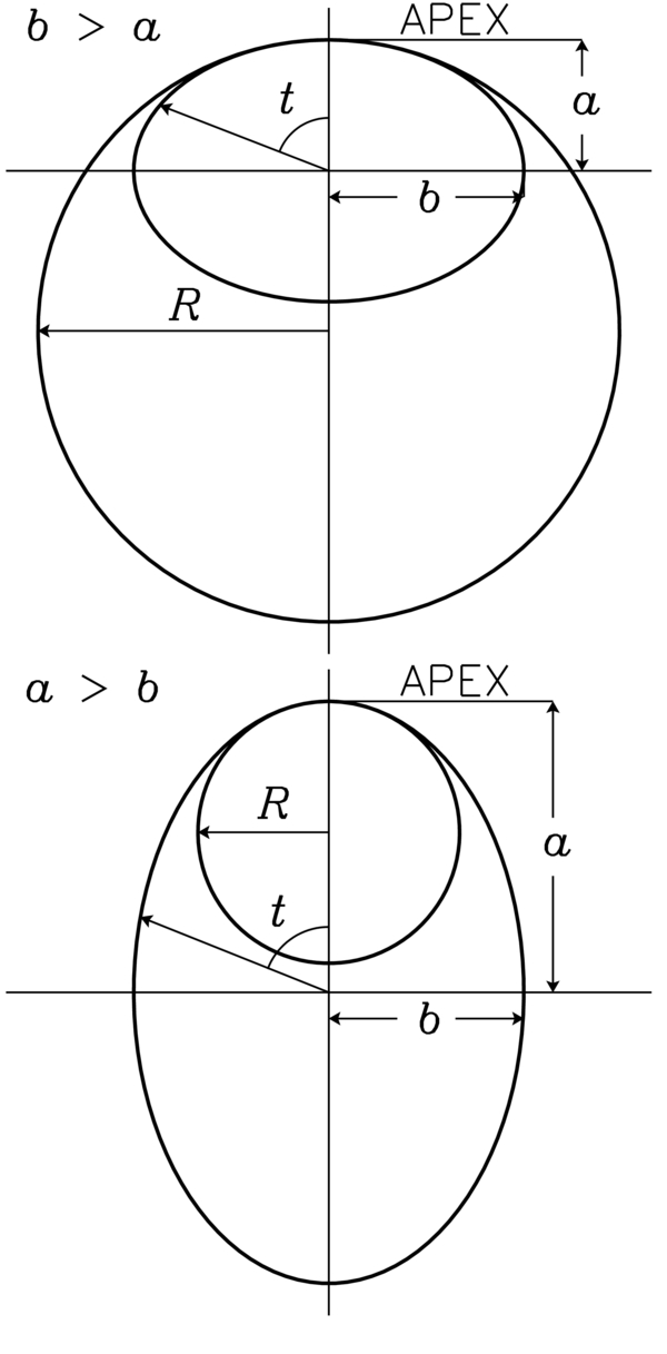
Figure 1. Ellipse configuration with a circle overlaid of equal radius of curvature as the ellipse at the apex. The top panel is the b > a case where R > a, and the bottom panel is the a > b case where a > R.
Download figure:
Standard image High-resolution imageFinally, using r,  , and
, and  , derived with the ellipse parametric equation at t = 0, and Equations (9)–(12), the Lorentz self-force at the apex of the ellipse can be derived. After a change of variables from s to t with Equation (2) we get
where
Finally, substituting Ω into  and
and  , eliminating higher order t0 terms, and using the following approximation:
the total force fE at the apex of the ellipse can be written as
3. RESULTS
G&C found that the Lorentz self-force on a segment of an arbitrarily shaped current loop, with small to moderate non-circularity, can be approximated with a torus having equal radius of curvature and minor radius diameter as that segment. In this section, the derived expressions for the Lorentz self-force at the apex of the ellipse are compared with the self-force of a torus current loop with radius of curvature equal to the local radius of curvature at the apex of the ellipse (and minor radius; i.e., R = b2/a). This scenario is depicted in Figure 1, where, when b > a, R > a, and when a > b, a > R. The expression for the Lorentz self-force on a segment of a torus is expressed as (Shafranov 1966)
Note that the similarity between fC and fE is that both equations contain a (1/R)ln(8R/ρ) term, except that fE has additional terms associated with the ellipse. In the limit where a → b the ellipse equation reduced to the torus equation, i.e., lima → bfE = fC, and a can be replaced by R. For comparison, we vary the eccentricity and use the local radius of curvature at the apex of the ellipse as the value of R in fC. The eccentricity (e) is defined as
It is seen that the eccentricity is found directly in Equation (22) in the atanh and atan terms.
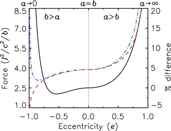
Figure 2 shows fC (dashed (red)) and fE (dot-dashed (blue)), normalized to I2/c2/b, plotted against eccentricity, where negative values indicate the b > a scenario, and the positive values the a > b scenario. The minor radius is set to ρ = a/10 for b > a, and to ρ = R/10 for a > b. The abscissa in Figure 2 is plotted in this way to show a smooth transition between the b > a and a > b scenarios, where the two scenarios overlap at a = b (equivalently e2 = 0). This is simply done by fixing b and varying a from ∼zero to ∼infinity. The solid (black) line is the percent difference between the ellipse and circular torus self-force, 100(fE − fC)/fE. For moderate values of eccentricity, fC can be used as an approximation for fE, for example, at e = −0.75, the percent difference is ∼2%, and at e = 0.75, the percent difference is ∼10%. It is found that the difference goes to infinity faster as a → 0 than for a → ∞. This is clearly seen in the plot because fC and fE diverge as a → 0.
Figure 2. Lorentz self-force, normalized to I2/c2/b, of the torus circle channel model (dashed (red)) and the ellipse current channel model (dot-dashed (blue)) plotted vs. eccentricity (e). Negative values correspond to the b > a scenario and positive values to the a > b scenario. For the calculation, b is held fixed while a is varied from ∼0 to ∼∞. The solid (black) line is the percent difference between the two models 100(fE − fC)/fE.
Download figure:
Standard image High-resolution image
4. CONCLUSION
In this work, we have derived an expression for the Lorentz self-force at the apex of an ellipse current loop. It is found that for moderate values of eccentricity, the self-force at the apex of the ellipse current model can be well approximated by a torus of equal radius of curvature as that of the local value of the ellipse. We have quantified this by showing that the percent difference is small for moderate values of eccentricity, and it is at the extremes that this difference grows large. This work effectively quantifies the approximation made by Krall et al. (2006) in their ellipse current channel model of CMEs. In their work they find that CMEs can be fitted with an ellipse of eccentricity between 0.70 and 0.83 (in the a > b case). Since they used the approach of using a torus model to approximate the force at the apex of the ellipse, according to Figure 2, this corresponds to ∼8% and ∼15% percent difference, respectively.
In an associated work, Olmedo et al. (2013) use the expression of the ellipse to approximate the force at the apex of a circular partial torus line-tied flux rope model with fixed footpoints and a prescribed radius of curvature. This approximation allowed them to readily solve a stability criterion of eruption of line-tied flux ropes. The approach taken by Olmedo et al. (2013) is opposite to that of Krall et al. (2006) who use a torus to approximate the force of an ellipse-shaped flux rope. Therefore the results of G&C, that the Lorentz self-force of an arbitrarily shaped current loop of small to moderate circularity can be approximated with a torus of equal radius of curvature as the local radius of curvature of that loop, can work both ways.
This research was performed while O.O. held a National Research Council Research Associateship Award at the Naval Research Laboratory, funded through NASA contract S-136301-y. J.Z. is supported by NSF grant ATM-0748003. O.O. thanks James Chen for many valuable discussions.