
ABSTRACT
We describe the design and performance of a near-infrared camera for use at the University of Wyoming 24 inch telescope at Red Buttes Observatory. The camera makes use of a HAWAII-2 2048 × 2048 pixel HgCdTe array, sensitive from 0.9–2.5 μm. The array is operated with a Generation III controller from Astronomical Research Cameras and makes use of a General Use Multi-Channel Preamplifier from IRLabs. The camera optics consist of a compact 1:1 re-imaging Offner relay with a cold pupil mask and includes a nine-position filter wheel driven internally with a cryogenically conditioned steppermotor. The primary objective was to develop a low-cost system for testing the HAWAII-2 array and electronics that were acquired for a larger project, while at the same time providing a temporary near-infrared camera for use at Red Buttes Observatory. In this article we present various aspects of the mechanical construction, optics, electronics, and performance.
Export citation and abstract BibTeX RIS
1. INTRODUCTION
We have begun the design and construction of a wide-field near-infrared (NIR) camera which makes use of a HAWAII-2 focal plane array. To aid in the development of this large-scale camera, a smaller test-bed version dubbed BIRCAM (Buttes Infra-Red CAMera) has been developed to implement and test the HAWAII-2 array and readout electronics. The HAWAII-2 array is a 2048 × 2048 HgCdTe array with 18 μm pixels sensitive from 0.9–2.5 μm with a peak quantum efficiency2 of ∼0.75 in the H band.
The commercial availability of large-format near-infrared arrays coupled with modest-sized research telescopes creates an opportunity for NIR synoptic observations of relatively bright galactic targets, and complements large single epoch NIR surveys like 2MASS (Skrutskie et al. 2006). Thus, in addition to being a test platform, BIRCAM was designed to be a fully functional, wide-field, NIR imager for use at the 24 inch telescope at the University of Wyoming's Red Buttes Observatory (RBO).
In § 2 we describe the design of the BIRCAM cryostat. In § 3 we describe the optical and mechanical design of a compact reimaging system. The HAWAII-2 controller electronics are described in § 4 and auxiliary electronics and software are described in § 5 and § 6, respectively. In § 7 we report the performance characteristics of BIRCAM at the Red Buttes Observatory.
2. CRYOSTAT DESIGN
BIRCAM was designed for use at the Cassegrain focus of the 24 inch f/8 DFM3 telescope at RBO. Based on the need to use as much existing hardware as possible, the cryostat for BIRCAM was modified from a NIR camera originally designed for prime focus at the Wyoming Infrared Observatory (WIRO), known as BABE (Spillar et al. 1990, Barnaby et al. 1994). The BABE cryostat was built as a "down-looking" liquid nitrogen (LN2) system with a 3 L capacity LN2 tank. BIRCAM's position at the Cassegrain focus at RBO required that the fill tube be extended into the tank to enable an "up-looking" configuration. The fill tube neck was also modified to include a fiberglass shunt to electrically isolate the interior from the cryostat/telescope ground which is tied to Earth ground, and thus eliminate possible ground loops, ground noise, or electrostatic discharge due to lightning from affecting the detector. The fan-out board ground plane is subsequently tied to the analog ground of the Generation III controller through the bias signal cable. Components that were reused from the BABE cryostat were: a calcium fluoride window, a set of 1 inch circular filters, the liquid nitrogen tank, and the getter can.
The cold plate and adjoining liquid nitrogen tank are rigidly supported with 12 fiberglass shafts that mount to a secondary rear flange within the cryostat. A 100 mL getter can is inserted into a cavity in the liquid nitrogen tank and can be accessed through a port in the rear flange. The getter can itself has a cold finger along the central axis to help cool the active getter material, zeolite. Our pump-down procedure includes heating the zeolite to 400°C for 2–3 hours and placing it in the cryostat immediately before the cryostat is pumped down to 10-4 Torr. Once liquid nitrogen is added to BIRCAM, the zeolite begins the sorption process and captures any outgassing in the cryostat and maintains vacuum to better than 10-4 Torr. The hold time for the cryostat is 24–30 hr depending on ambient conditions.
To accommodate the internal optics, the original BABE cryostat was lengthened by adding a 4 inch extension. A new cold shield was manufactured to encompass the internal optics, filter wheel, and detector array, and to allow for intermediate electrical connectors, see Figure 1.
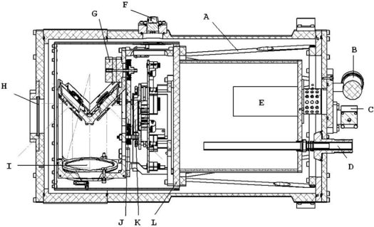
Fig. 1.— Cross-sectional view of BIRCAM.A. One of 12 fiberglass struts that holds a collar though which the cold plate and adjoining LN2 tank are supported. B. Vacuum gauge. C. Vacuum valve. D. A fill tube to allow up-looking operation. E. Getter can for holding zeolite. F. One of four hermetic electrical connectors. G. Stepper motor for moving the filter wheel. H. Calcium fluoride window. I. The primary mirror for the Offner relay. J. Nine-position filter wheel. K. The HAWAII-2 array. L. Cold plate.
3. OPTICAL DESIGN
The HAWAII-2 array is sensitive from 0.9–2.5 μm and thus requires reimaging optics and a cold pupil stop to mask thermal radiation from regions outside the telescope pupil from reaching the detector.
The optical design chosen for the camera was an Offner relay, based on its excellent 1:1 imaging performance. This feature of the Offner relay has made it a popular choice for other near-infrared cameras of this scale (Graham & Treffers 2001, Fischer et al. 2003, Persson et al. 2002, Murphy et al. 1995). To make the Offner relay as compact as possible, the light path was folded using two elliptical flats as fold mirrors (see Fig. 2. In an Offner relay, the secondary mirror should nominally have half the radius of curvature as the primary. However, given our goal of producing a quick and relatively inexpensive camera, we chose to use commercially available optics over custom optics. A primary and secondary were found that were closely matched (see Table 1), although the secondary radius of curvature is slightly less than the primary focal length with the result that the optical design suffers from a small amount of residual astigmatism. The ZEMAX optical design software was used to refine the optimum separations of the mirrors, yielding the best rms spot size at wavelengths of 1.2, 1.8, and 2.2 µm. The principle focus from the telescope is located 12 mm inside the cryostat with respect to the inside surface of the calcium fluoride window. At this location, the cold shield has a 1 inch circular aperture which acts as a field stop, preventing stray thermal radiation from entering the system. RBO is located at 7200 feet and hence is a reasonably good infrared site; however, it is built at ground level and the ambient seeing conditions typically deliver 2–3'' FWHM seeing. With a 43'' mm-1 plate scale, this FWHM corresponds to roughly 70 µm such that the modest astigmatism has little impact on the performance of BIRCAM. The full HAWAII-2 array is 37 mm × 37 mm and would require optics larger than can be accommodated within the BIRCAM cryostat. As a result, the optics illuminate only one quadrant of the array; see Figure 3. However, this has no impact on our goals of testing the HAWAII-2 array and electronics, and still enables interesting synoptic survey science to be undertaken at RBO. The resulting field view is 13 × 13' with modest vignetting; see Figure 4.
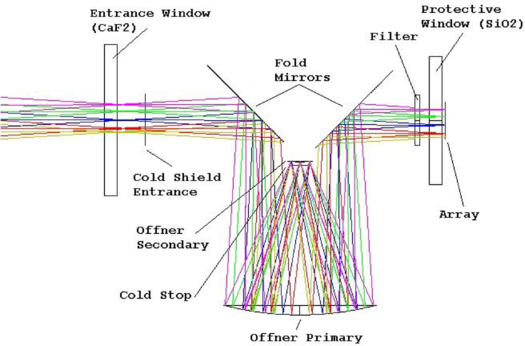
Fig. 2.— Optical design of BIRCAM showing the folded path of the Offner relay. Light enters through the cryostat entrance window and passes through a hole in the cold shield, which acts as a field stop between the window and first fold mirror. The fold mirrors allow the Offner relay to be rotated to fit within the limited confines of the BIRCAM cryostat and minimize stray radiation from reaching the detector, shown on the right.
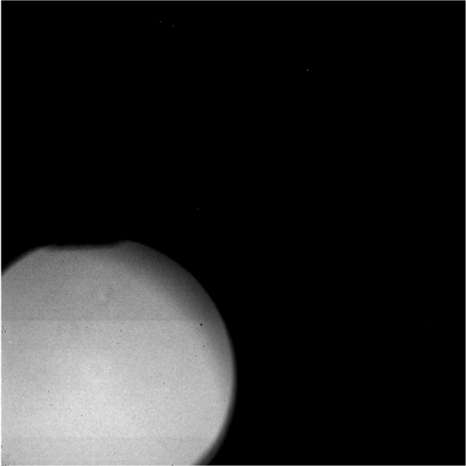
Fig. 3.— BIRCAM flat field showing vignetting of the 1 inch circular filter aperture. The three superfluous quadrants are cropped from the raw data before processing.
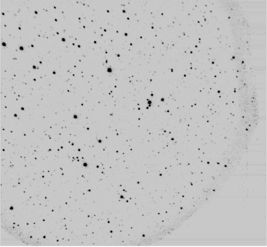
Fig. 4.— BIRCAM field of Galactic Cepheid AA Serpentis showing the cropped field of view, North is up.
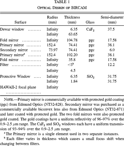 |
The optics are mounted within an optical bench machined from a single piece of aluminum to minimize interfaces and alignment difficulties and to create a homogenous structure; see Figure 5. Also, the aluminum bench was thermally cycled in liquid nitrogen prior to final machining in order to minimize internal differential expansion. Each mirror is preloaded against the bench using a wave-disc spring washer. Individual cover plates press against the edge of the mirrors and are held in place with adjustable nuts, allowing for optical alignment. The cover plate for the secondary doubles as the cold pupil mask.
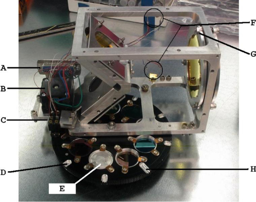
Fig. 5.— Optical bench with filter wheel in place showing the following components. A. DB-25F connector. B. Cryogenically conditioned stepper motor. C. Two microswitches. D. One of eight short grooves to toggle the outer microswitch. E. An aluminum filter blank. F. Two diodes which act as temperature sensors. G. One of the adjustment nuts for the primary mirror of the Offner relay. H. The long home position groove which toggles both microswitches.
A filter wheel, with nine 1 inch circular positions, is mounted on the bottom of the optical bench and is turned with a stepper motor also mounted on the optical bench. The filter wheel contains J, H, and K broadband filters; see Figure 6. The motor is a commercially available stepper motor, which was stripped of grease and is run dry in the cryogenic environment. Two microswitches are mounted on the bench and their lever arms roll along the top surface of the filter wheel where short grooves have been cut to indicate filter position. The home position groove is longer than the others, which allows both switches to be triggered. Power to the motor is turned off in software after positioning, and the switches act to hold the filter wheel in place.
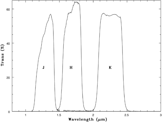
Fig. 6.— Instrumental throughput of the J, H, and K filters (at room temperature), which includes the transmission of both windows and a total of five reflections from the gold coated mirrors. No account is taken for atmospheric transmission or detector quantum efficiency.
The optics bench has three adjustable hard points that push against a three-point kinematic mount containing the HAWAII-2 array. The kinematic mount bolts directly to the cold plate and has three threaded posts on which the fan-out board and a cover plate are preloaded using stainless steel springs. The cover plate is designed such that the optics bench pushes against it to square and align the array to the optical axis. A SiO2 window was added to the cover plate to prevent damage to the detector array; see Figure 7. It was decided that as a test bed instrument, it might be necessary to open the camera several times during its development, and the window would provide additional protection to the array and be worth the small loss in throughput.
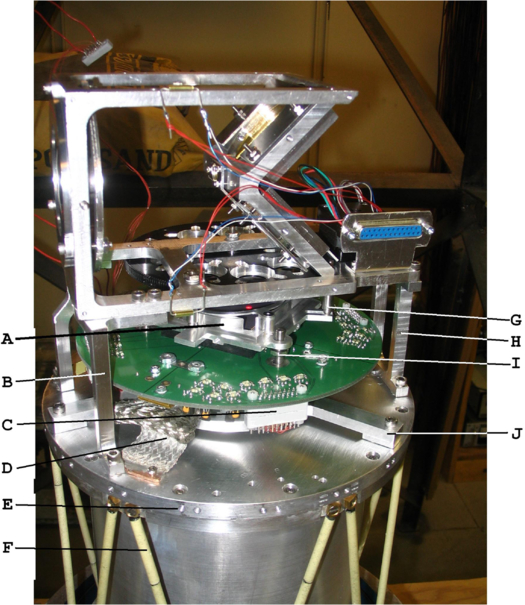
Fig. 7.— Optical bench mounted on the cold plate with the kinematic mount containing the fan-out board. A. The cover plate that fits over the HAWAII-2 array which contains a protective window. B. One of the standoffs that hold the optics bench in place. C. One of four 26 pin connectors that attach to the fan-out board. D. Cold strap to facilitate cooling. E. The outside edge of the cold plate where the cold shield gets mounted. F. One of 12 fiberglass support struts. G. One of the three hard-points on the optics bench which press against the cover plate to square the array to the Offner optical axis. H. One of the standoffs that hold the optics bench in place. I. One of three threaded posts on which the fan-out board and cover plate are preloaded. J. One of three support arms that hold the kinematic mount in place.
The modular design of BIRCAM allows the optics to be aligned outside of the cryostat. Once aligned, the optical bench assembly can be placed within the cryostat as a single module. The procedure for alignment was as follows: A laser reflecting off a plane mirror was used to define an optical axis. The Offner relay module was then placed above the plane mirror and its mirrors were adjusted such that the beam both intersected the center of the Offner secondary and returned to its source. Since the Offner relay is symmetrical, the bench was then rotated and the alignment procedure repeated. Once the alignment converged in both orientations, the initial optical alignment was complete.
The optical bench was designed to hold the mirrors in a nominal position that was predetermined using ZEMAX optical design software. The final positions were adjusted empirically by imaging an optical resolution chart onto a small commercial CCD camera until the optimum image quality was achieved. Details of this procedure can be found in Monson (2009). Once aligned, the optical bench was placed in the cryostat over the kinematic mount containing the HAWAII-2 array. The optical bench attaches to the cold plate on two aluminum standoffs which provide a rigid mount and facilitate cooling of the bench. Indium was placed at each interface to increase thermal contact. A final image quality check at the telescope revealed no signs of any alignment shift from the cool-down, and BIRCAM began regular operation at RBO.
4. ELECTRONICS
The HAWAII-2 array was purchased from Teledyne Scientific and Imaging, LLC for a large NIR imager currently under development at the University of Wyoming. The HAWAII-2 array mounts in a Ziff socket on a fan-out board (designed by John Geary, SAO/CfA). The camera control electronics were purchased from IRLabs Inc. and include a General Use Multi-Channel Preamplifier (GUMP and a Generation III controller from Astronomical Research Cameras (ARC).
The HAWAII-2 array consists of four independent quadrants, each with eight output channels. The array can be read out in either a quadrant mode or in a 32-channel mode for a faster readout. The 32-channel mode is used for BIRCAM to minimize the background counts in the K band. The fan-out board uses off-chip amplifiers to eliminate the glow from the HAWAII-2 on-chip amplifiers. The back side of the HAWAII-2 array chip carrier consists of a 19 × 19 pin grid array where only the outer two rows of the array are used for signals, and the remaining interior pins are used for cooling. The thermal plane of the fan-out board connects the inner pins of the HAWAII-2 array to cold straps which attach to the cold plate. Four 10Ω, 10 Watt capacity surface mount power resistors are attached directly to the thermal plane of the fan-out board and provide for temperature control of the array.
The output signals from the fan-out board are brought out to the IRLabs GUMP preamplifier which attaches directly to the side of the cryostat. The GUMP preamplifier contains four daughter boards, one for each quadrant, each with eight channels. The preamplifier provides a noninverting 5 times gain and software programmable DC offset voltages. The GUMP output enters the ARC Gen III controller where 32 signal chains on four independent video boards provide an inverting gain of 2.5 and a software selectable DC offset voltage for each channel. The analog signal is digitized via a 16 bit A/D converter and is multiplexed with the other channels and transmitted over 250 MHz fiber optic cable to a PCI card on the host control computer. BIRCAM is typically run with 32 output channels using a singe correlated double sample resulting in a readout time of 1.3 s. The array performance was optimized by adjusting the programable bias voltages provided by the Gen III controller. This procedure is described in more detail in Monson (2009).
One effect we encountered while optimizing the array performance was the appearance of random hot pixels when the array was powered during cool down. To eliminate the effect, power to the array is kept off during cool down from ∼120 K to ∼90 K to eliminate this trapped charge. We found that the array can be powered up at any point before it reaches ∼120 K in order to verify that it is functioning, but it must be powered down before a temperature of ∼120 K is reached. If this is not done, the array will contain hot pixels or even appear saturated. This is removed only by heating up to ∼120 K and then cooling down again. The array can subsequently be powered down and back up without any obvious hot pixels so long as it has been kept below ∼120 K. We operate the HAWAII-2 array at a nominal temperature of 77.1 K (see § 5).
5. AUXILIARY ELECTRONICS
A commercial Galil DMC-4080 motor controller is used to control the filter wheel stepper motor and sense the state of the filter wheel microswitches. A Lakeshore 340 temperature controller is used to control the array temperature and monitor the temperature at three other positions within the cryostat. A LabView interface was developed to handle the communications with each controller.
The temperature of the array is monitored with a Lakeshore DT-471(LR) silicon diode mounted in a small copper block on the thermal plane of the fan-out board adjacent to the Ziff socket holding the HAWAII-2 array. Three 1N4001 diodes are used as additional temperature sensors, one on the cold plate and two on the optics bench. The temperature of the array is servo regulated by the Lakeshore 340 using four heater resistors mounted on the thermal plane of the fan-out board. The Lakeshore 340 is hardware-configured not to exceed 0.5 A on the heater loop and the LabView software is designed to prevent the Lakeshore 340 from supplying more than 156 mW, which is enough to heat the HAWAII-2 array. During normal operation, the HAWAII-2 array is run at 77.1 K with a typical rms of ∼50 mK.
The LabView software on the host computer communicates with the motor controller and temperature controller via a SENA PRO (PS410) Ethernet to serial switch. The PS410 can handle four serial (RS232/422/485) devices up to 230 Kbps and is configurable over the Internet. The software allows the user to monitor the various temperatures and to verify the filter wheel position and operation (see § 6).
6. SOFTWARE
Communication with the Gen III controller is handled using VOODOO, a C/JAVA-based GUI software interface provided by ARC. On start-up, VOODOO loads a customized timing file to the Motorola 56300 Family DSP of the Gen III controller, which in turn supplies the appropriate bias voltages to the HAWAII-2 array and reset signals that continuously reset and flush the array during idle operation. The VOODOO source code was modified to include an option to correctly deinterlace the 32 outputs and reconstruct the image uploaded from the controller, as well as to include filter and array temperature header information supplied from LabView. The instrument control interface for BIRCAM was developed using LabView 7.1 for Linux. The LabView interface communicates with the controllers through the PS410 over Ethernet using the specified IP address of the PS410 and port number assigned to the temperature and motor controllers. The Linux environment was chosen to allow quick look at the data via IRAF while at the same time providing an efficient instrument control environment, all using a single computer. A single i686 Intel(R) Pentium(R) 4 CPU 2.66 GHz machine running the Mandrake 2.6.12-23 mdk kernel is used for all BIRCAM functions at the observatory.
7. CAMERA PERFORMANCE
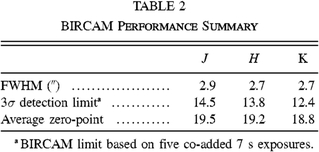
BIRCAM began regular operations in 2008 January at RBO. The typical seeing at RBO ranges from 2–3'' FWHM in the optical, and this is also seen at J, H, and K. The seeing was expected to improve at NIR wavelengths; the lack in improvement is due to aberrations resulting from the use of nonoptimized commercial optics, see § 3. The resultant seeing is such that the 0.76'' pixel-1 plate scale adequately samples the point-spread function (PSF), and while the larger NIR camera was under development, BIRCAM was used for conducting an extensive survey of Northern Galactic Cepheids (Monson 2009). CIT-CTIO IR standards have been used for calibration (Elias et al. 1982), and the results are summarized in Table 2.
 |
There is a strong gradient in the K band images, a result caused by thermal emission from within the cryostat. In retrospect, it is believed that the source of the radiation is from the mirror cover of the second fold mirror in the Offner relay, which was not heat sunk or positioned correctly; also, the fact that BIRCAM used an original wide K band filter instead of the more recent K-short filter means that BIRCAM was more sensitive to thermal background emission. (The original K filter used in BIRCAM was reused from the filter set in the BABE camera to reduce cost). The thermal emission from the mirror cover was filtered out in the J and H bands; however, a very small light leak was still present in the images, a result believed to be due to poor baffling of the array from the side. With the goal of testing the HAWAII-2 electronics, and limited time available before the array was needed for the large camera, the decision was made to forgo the pursuit of an "ideal" camera and begin the scientific endeavor envisioned for BIRCAM. Flat fields in the K band were made by differencing flats taken at different times (before and after twilight) to remove the internal component and leave a uniform background. As such, the background is reported graphically in Figure 8, which includes all sources of background flux because the flux from the sky could not be distinguished from the total background flux in a sensible way with the data obtained. All these effects contribute to the K band data being of lower quality than the J and H data; see Monson (2009) for more details.
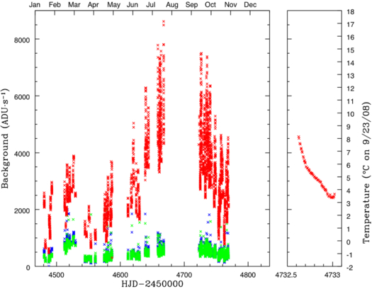
Fig. 8.— Background count rates for J (blue), H (green), and K (red) bandpasses at RBO. Backgrounds for the J and H bands are due to OH airglow, while the K background is dominated by the thermal background, which is clear in the summer months. The vertical traces actually decrease slightly to the right, a result of the background counts decreasing from sunset to sunrise as the temperature drops, as can be seen in the plot at the right.
The dark current4 is less than 0.1 electron s-1 and the read noise is ∼16 electrons for one nondestructive read (23 electrons for a correlated double sample [CDS] read). This was measured empirically by taking pairs of CDS images over a range of exposure times and computing the difference between pairs of common exposure times. The variance was plotted against the median count level of the pair to find a gain (inverse slope) of 115 e-1 ADU-1. The gain was multiplied by the standard deviation in a short-exposure CDS image to find the read noise. Our value is consistent with documentation provided by Teledyne for our specific array, which quotes 19.87 electrons.
Typical imaging at RBO includes taking multiple exposures of each target with small telescope offsets introduced between each exposure. Twilight flat fields are applied to each image and then each image set is median combined before aligning to determine background levels. The frames are background subtracted and then the individual frames are aligned and combined using the IRAF task XDIMSUM; details can be found in Monson (2009).
8. SUMMARY
We have developed a compact near-infrared imager for use on the 24 inch telescope at the University of Wyoming's Red Buttes Observatory. The camera was designed as a low-cost system to test the 2048 × 2048 HAWAII-2 HgCdTe array and electronics that will be used in a larger instrument currently under development. The camera makes use of a compact Offner relay as a reimaging optical system enabling one quadrant imaging with the HAWAII-2 array. The camera contains a 9-position filter wheel with J, H, and K filters, and began operation at RBO in 2008 January. The telescope and camera deliver 2–3'' FWHM imaging over a 13' field of view with a typical photometric accuracy of 2%.
We would like to thank Steve Hodder (UW), as head machinist for BIRCAM; Robert Howell (UW) for his enthusiastic support, advice, and contributions to this project; and John Geary (SAO/CfA) for kindly providing the fan-out board and advice for operating the HAWAII-2 array. We acknowledge, with thanks, Paul Johnson (UW) for providing the BABE cryostat from which BIRCAM was made. We thank and are grateful for time and support provided by Ron Canterna, Director of RBO, and for the telescope and instrument support provided by Chris Rodgers and Eric Hausel (UW). Funding for this project was provided through a grant from the National Science Foundation (NSF/MRI 0421507) and through institutional support provided by Bill Gern (VP for Research, UW) and the State of Wyoming.
Online Material
- Figure 2
- Figure 5
- Figure 7
- Figure 8
Footnotes
- 2
QE documentation was provided by Teledyne for this specific array.
- 3
DFM Engineering, Inc. Longmont, CO.
- 4
Documentation provided by Teledyne for this specific array.