


Abstract
We have studied the method for suppressing speckle noise in patterns produced by a laser based on a fast-response electro-optical cell with a ferroelectric liquid crystal (FLC) in which helicoid is absent, i.e., compensated for. The character of smectic layer deformation in an electric field is considered along with the mechanism of spatially inhomogeneous phase modulation of a laser beam passing through the cell which is accompanied by the destruction of phase relations in the beam. Advantages of a helix-free FLC cell are pointed out as compared to helical crystal cells studied previously.
Export citation and abstract BibTeX RIS
1. Introduction
The problem of speckle noise in patterns produced by a laser beam is usually solved by breaking (averaging) phase relations in the beam prior to projecting images to a screen under fast (above  ) spatially inhomogeneous phase modulation with the depth on the order of
  and greater. The device for suppressing speckle noise should have a high resolution capability (on the order of hundred and even thousand
  ) because of the necessity of the subsequent broadening of the beam. It also should not worsen the beam intensity and directivity.
Initially a despeckler was a rotating phase mask with a random spatial distribution of phase [1, 2]; in paper [3] it consisted of two diffusers rotating in opposite directions with different angular velocities and a spatial filter, which limited the opening of the scattering cone and speckle decorrelation. A similar system, which has been implemented in the form of a device by Power Technology Inc. [4], had a collimator with three spatial filters (with the cone opening of  ,
,  and
and  , respectively) for making the despeckler possibilities wider. Such a system can hardly be made compact; in addition, it has high losses of light. The employment of a spatial light modulator which forms orthogonal functions [5 – 7] strongly complicates the optical system and makes it expensive. A photopolymer medium [8], in which numerous speckle-images were successively recorded in the form of superimposed phase holograms, exhibits high efficiency of speckle suppression but is noisy, critical to wavelength variation and 'fatigues' in the process of operation. Finally, only the despeckler [9, 10] made in the form of a thin moving medium vibrating at a frequency of approximately
  with the amplitude of
  is widely used. However, even this method is characterised by unstable operation and 'fatigue' of the material.
The method of spatially inhomogeneous phase modulation of light in a single-pixel electro-optical cell suggested in [11, 12] utilises electrically controlled birefringence of a ferroelectric liquid crystal (FLC) with a spiral (helical) structure. An alternating electric field was applied across the cell simultaneously at low and high frequencies, which caused spatial deformations of the helicoid (without affecting its pitch) in an FLC layer. As a result, the position of the principal optical axis of the refractive index ellipsoid randomly varied with respect to the direction normal to smectic layers. The arising small-scale fast-varying structures with a random distribution of refractive index gradients resulted in phase modulation of passing light which became spatially inhomogeneous over the cell aperture at a high spatial resolution (on the order of the pitch scale, i.e., a fraction of  ).
).
Yet this despeckler has drawbacks. The deformed helical structure of molecules has been found to change the spectral composition of radiation under phase modulation of light. In addition, after the electric field has been switched off there still remains residual scattering caused by the helix. The modulation frequency of light in a FLC cell at the electric field tension of  is limited by the value of
  which hampers possible applications of this modulation type. Finally, the control electronic circuit generates voltage pulses of different shapes which is not optimal.
The present work is aimed at obviating the obstacles mentioned above. This problem has been solved by using another type of an FLC, namely, a helix-free (spiral-free) FLC in which the helical winding of molecules is completely compensated for by the interaction of chiral additives having opposite signs of optical activity [13].
2. Deformation of smectic layers in a helix-free FLC cell
Principally the design of electro-optical FLC cells used in new experiments on spatially inhomogeneous phase modulation of light was similar to that employed previously [11, 12]. The cells were filled with a helix-free FLC having the following parameters: spontaneous polarisation,  ; rotation viscosity coefficient,
  ; tilt angle of the molecule in smectic layers,
  (at a temperature of
  ); and temperature of existence of ferroelectric phase, from
  to
to  . This material exhibits a fast response: the times of electro-optical response switching on/off are in the sub-millisecond range [14]. The thickness of liquid crystal cells varied from 10 to
  , and the cell aperture was
  .
.
At a certain relationship between the spontaneous polarisation, rotational viscosity and the elasticity modulus of the FLC which determines the deformation along smectic layers, in a cell with a helix-free FLC without an electric field periodic deformations of FLC smectic layers may arise, resulting in periodical variations of the position of the director (the main axis of refractive index ellipticity) along each smectic layer [14]. When the orientation of the FLC director is homeotropic, i.e., smectic layers are parallel to the substrates of an electro-optical cell, the periodic deformations of smectic layers are observed as alternating light and dark strips (Fig. 1a) with the period varying from 1.5 to  , which depends on the molecular structure of the FLC. The state of the FLC in a weak electric field where the strips start to vanish is illustrated in Fig. 1b.
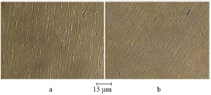
Figure 1. Periodic deformations of smectic layers in a helix-free FLC (a) without an electric field and (b) in an electric field  . The director orientation is homeotropic (smectic layers are parallel to the substrates of the electro-optical cell); polaroids are crossed.
Download figure:
Standard imageIn Fig. 2 one can see the scheme which explains deformation of smectic layers in a helix-free FLC and fragment (right) illustrating the mutual disposition of the spontaneous polarisation vector of a smectic layer and the FLC director. In the electro-optical cell of thickness  the smectic layers ( 1 ) of thickness
  are placed between glass substrates ( 2 ) (the remaining layers of the cell are not shown).
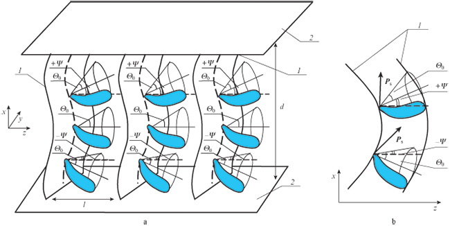
Figure 2. (a) Scheme explaining deformation of smectic layers in a helix-free FLC and (b) fragment illustrating the mutual disposition of spontaneous polarisation in a smectic layer and FLC director.
Download figure:
Standard imageDeformations of this kind mean that when the electric field is absent in smectic layers, the FLC molecules, which are initially inclined at an angle  with respect to the layer normal at this point, are additionally inclined at a certain angle
  with respect to the
  axis. As a result, the director projection onto the plane
  is changed. In this case, the director may be redirected due to the interaction between an alternating electric field
  and spontaneous polarisation
  (the field is applied along the
  coordinate) in two ways: (i) the director changes its azimuth angle
  by
by  and is redirected over the generatrix of the cone with the angle of opening
  (with the characteristic time
  [15] independent of the frequency of the electric field variation); and (ii) the distribution of the angle
  , related to the deformation of smectic layers, changes.
In the first case, the dissipation coefficient is the rotational viscosity  , and in the second case, where the frequency of the electric field variation is
  (here
(here  is the Maxwell relaxation time), the dissipation coefficient is the viscosity of share deformation
  [16]. Thus, the alternating electric field
  acting along the smectic layers (
 coordinate) interacting with the spontaneous polarisation changes the distribution of angle
  . Physically this means the change of type of energy dissipation and transfer from the characteristic coefficient
  to
to  .
.
A nonlinear variation in the distribution of angle  in an alternating electric field results in the origin of a soliton, which is a wave packet that contains a localised periodic wave inside. The velocity of soliton centre motion is defined [17] as
where  is the coefficient of elasticity, which describes the deformation of the director with respect to the angle
  ;
;  is the share viscosity of the FLC;
  is the bend energy of smectic layers; and
  is the initial angle of director orientation.
Moving solitons redirect the director in a whole volume of the FLC. As a result, the azimuth angle  in all smectic layers becomes the same and equals zero or
  depending on the direction of the electric field; the vector
  takes the direction of the electric field. In this case, if the polarisation plane of incident light is parallel to the FLC director (along the main optical axis), then the light transmission of the electro-optical cell is maximal. Inversion of the electric field sign (the control voltage polarity) again induces generation of soliton waves which is accompanied by light scattering.
As was mentioned, periodic deformations of smectic layers of a helix-free FLC arise at a certain relationship between the spontaneous polarisation, rotational viscosity and the corresponding modulus of elasticity, namely:  is no greater than
  ,
,  and the modulus of elasticity
  which determines the deformation along smectic layers is within the limits
  .
.
If  , then there is no transfer to the share viscosity
  and the soliton mechanism of FLC director reorientation is not realised; at
  the optical response time noticeably increases not only at low but also at high frequencies where the share viscosity
  becomes responsible for the energy dissipation. With increasing
  above
above  the saturation tension raises and ferroelectric domains arise [18] (along the
  coordinate in Fig. 2), which results in light scattering when the electric field is switched off. Finally, the range
 for the elasticity modulus
  characterises the interval in which the smectic layers are stable and, however, capable of generating periodic spatial deformations in the absence of an electric field.
Thus, under the conditions mentioned above, periodic deformations of smectic layers arise in the electro-optical cell with a helix-free FLC and, as a consequence, the director (the main optical axis) periodically changes its position along every smectic layer.
3. Mechanism of spatially inhomogeneous phase modulation of light
At a certain relationship between the period of smectic layer deformation, the thickness of an electro-optical cell and the amplitude and duration of control voltage pulses, the arising soliton wave may cause gradients of the refractive index along the smectic layers and intense light scattering.
The efficiency of light scattering  (contrast ratio) on the soliton waves which arise when the angle distribution
  nonlinearly varies in an alternating electric field is shown in Fig. 3 as a function of the duration of the alternate-sign control voltage pulses with an amplitude of
  applied to a
  -thick helix-free FLC cell.
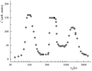
Figure 3. Efficiency of light scattering of an electro-optical helix-free FLC cell vs. pulse duration of control voltage at a fixed pulse amplitude.
Download figure:
Standard imageIn the case considered (at the corresponding relationship between the amplitude and duration of alternate-sign control voltage pulses, the period of smectic layer deformation and the spontaneous polarisation of the FLC), the process of scattering is of bistable character and both optical states of a cell (with the maximal transmittance or maximal scattering) are kept for a few seconds after switching off the electric field or until the arrival of the pulse of opposite polarity.
Depending on the duration of the electric field action on the FLC structure (the duration of control voltage pulses  ) several maxima of scattering efficiency are observed (see Fig. 3). The angle between the polarisation plane of incident light and direction of the main optical axis of the FLC, which corresponds to maximal efficiencies of light scattering and transmission, takes a maximum value
  at a pulse duration of
  and reduces for the second and third maxima (
 and
and  , respectively). The regular structure of scattering centres in the form of circular domains corresponds to a maximal efficiency of light scattering [the first maximum of
  ] [19].
The transitions between scattering modes under the action of control voltage pulses with a duration corresponding to various maxima of light scattering cause the scattering indicatrix to chaotically change its position. The result of the short-time  switching on of scattering is that spatially inhomogeneous structures with an actually random distribution of refractive index gradients are formed over the whole volume of the FLC layer, which, in turn, is the reason for spatially inhomogeneous (in the beam cross section) phase modulation of light in the electro-optical cell. Note that such short-time light scattering is not recognised by eyes, does not distort image structures, has no effect on image perception and the losses to such scattering are negligible (less than 5 %).
Analysis of light radiation passed through the cell shows that in the cell with a helix-free FLC there are no distortions in the spectral composition of radiation and no scattering after switching off the electric field which have been observed previously in a helical FLC. This is the advantage of a new material which widens the field of its application.
4. Destruction of phase relations in a laser beam
The spatially inhomogeneous modulation of phase delay with the depth on the order of  and greater allows one to destroy phase relations in the laser beam passing though the electro-optical cell and, hence, to suppress speckle noise in an image. For a particular radiation wavelength, the depth of phase modulation is determined by the FLC birefringence coefficient
  , the electro-optical cell thickness and the control voltage amplitude. In an
  -thick cell a maximal modulation depth
  is attained at a voltage amplitude of
  .
.
From the viewpoint of speckle suppression the optimal relationship between the frequency and depth of light modulation and the capability to produce, in a FLC layer, spatially inhomogeneous structures with a random distribution of refractive index gradients has been achieved at a certain ratio of the FLC layer thickness and the period of smectic layer deformation. For the deformation period of  the optimal thickness was
  .
.
The distribution of refractive index gradients over a FLC volume and, hence, the character of the phase modulation delay, substantially depend on the ratio of the duration and the amplitude of control voltage pulses. The oscillogram of an electro-optical response (Fig. 4, bottom) illustrates spatially inhomogeneous phase modulation of light with the depth of up to  in a helix-free FLC cell. One can see that at the electric field tension of
  highly inhomogeneous phase modulation is attained when the low-frequency voltage (meander) is modulated by alternating-sign pulses of duration by an order of magnitude shorter than the period of a low-frequency signal (two top oscillograms). Here the low-frequency signal (meander) with an amplitude of
  had the pulse repetition rate of
  , whereas the frequency of the modulating signal of the same amplitude was
  . The amplitudes and frequencies of pulses were chosen in such a way that the efficiency of light scattering varied during every pulse in a series, however, not reaching a maximum value.
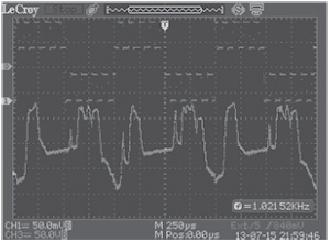
Figure 4. Oscillograms of the control voltage applied to the helix-free FLC cell (top) and of the optical response – phase delay modulation (bottom).
Download figure:
Standard imageThe consequence of the chosen mode of electrical excitation is destruction of phase relations in the laser beam passing though the electro-optical cell. This is illustrated in Fig. 5 where a photograph of the radiation intensity distribution is shown in a transverse cross section of the laser beam passed through an  -thick electro-optical cell when the FLC is excited by a pulse of control voltage (the pulse shape is similar to that in Fig. 4). The repetition rate of low-frequency pulses (meander) was
  at an amplitude of
  ; the frequency of modulating signal (alternating-sign pulses of the same shape) was
  at an amplitude of
  . The efficiency of speckle noise suppression was 50 %; this value may be enhanced in further optimisation of the composition and thickness of the FLC layer, cell design and supplying electrical signal.
Figure 5. Photograph of the radiation intensity distribution in the cross section of the laser beam passed through the electro-optical helix-free FLC cell under the action of the voltage pulses shown in Fig. 4.
Download figure:
Standard image5. Conclusions
An optical modulator (despeckler) is suggested on the basis of an electro-optical helix-free FLC cell. The effect of phase modulation of light, which is spatially inhomogeneous over the aperture, in a FLC layer is attained by simultaneously applying high-frequency (up to  ) and low-frequency (up to
  ) pulses of source voltage; the frequency interval of light modulation at the electric field intensity of
  is twice greater than that in [11] and reaches
  , which makes the range of possible applications of the modulator (despeckler) wider. The main advantages of the spatial modulator are the absence of distortions in the spectral composition of modulated radiation and absence of light scattering after switching off the electric field. In addition, similar shapes of low- and high-frequency voltage pulses (meander) simplified the control electronic scheme of modulator. The work on investigating and optimising optical characteristics of the modulator with the aim of employing it as despeckler will be continued.
Acknowledgements.
Authors are grateful to the Russian Foundation for Basic Research (Grant No. 14-07-00185-a) and the Physical Sciences Division of the Russian Academy of Sciences (Program of Fundamental Researches II.5 'Physics of new materials and structures') for the financial support.